Pod type electric shaftless pump jet propeller

A pod-type propeller technology, applied in the direction of rotary propellers, ship propulsion, propulsion components, etc., can solve the problems of difficult installation and maintenance, long transmission shaft, bulky power system, etc., to achieve simple structure and avoid installation Maintain Complex Effects

Pending Publication Date: 2020-01-17
陆一霆
View PDF2 Cites 16 Cited by
  • Summary
  • Abstract
  • Description
  • Claims
  • Application Information

AI Technical Summary

Problems solved by technology

The transmission shaft of the existing oil-powered propeller is generally long and needs to be equipped with a reducer, resulting in a bulky power system, and the steering system or differe

Method used


Image

  • Pod type electric shaftless pump jet propeller
  • Pod type electric shaftless pump jet propeller
  • Pod type electric shaftless pump jet propeller

Examples


Embodiment 1

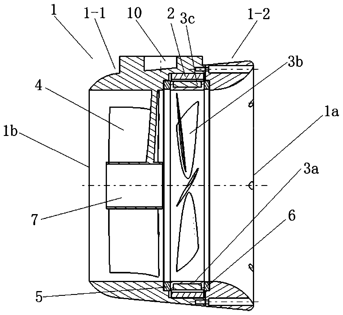
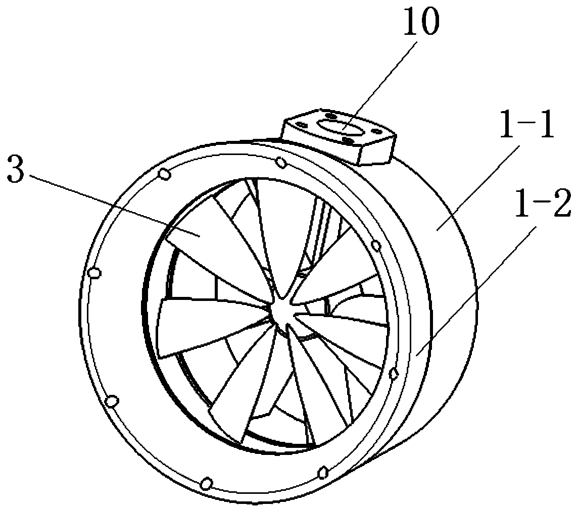
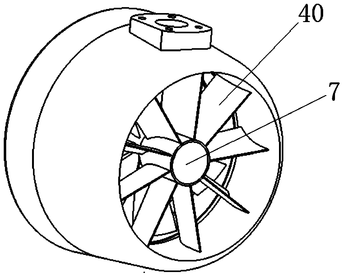
[0023] Such as Figure 1-4 As shown, the pod-type electric shaftless pump jet propeller of this embodiment includes a guide pipe 1 , a stator 2 , a blade rotor 3 , a guide vane set 4 , a first bearing 5 and a second bearing 6 .

[0024] Wherein, the guide tube 1 is a trumpet structure with openings at both ends, and the diameter of the water inlet 1a at the upstream end of the guide tube is larger than the diameter of the nozzle 1b at the downstream end of the guide tube, so as to improve the power output of the propeller. Wherein, the guide pipe 1 is an assembled structure, including a left pipe body 1-1 and a right pipe body 1-2, the spout 1b is located at the left end of the left pipe body 1-1, and the water inlet 1a is located at the right end of the right pipe body 1-2 , the inner side of the right port of the left pipe body 1-1 has a bearing groove for installing the first bearing 5 and an annular groove for installing the stator 2, the first bearing groove is located on...

Embodiment 2

[0037] The difference between the pod type electric shaftless pump-jet propeller of this embodiment and the first embodiment is that:

[0038] The radial sections of the hollow cylinder and the draft tube in this embodiment are asymmetric structures, which can also increase the structural rigidity and realize the structural diversification of the pod-type electric shaftless pump jet propeller.

[0039] Other structures can refer to Embodiment 1.

Embodiment 3

[0041] The difference between the pod type electric shaftless pump-jet propeller of this embodiment and the first embodiment is that:

[0042] In this embodiment, the design of the hollow cylinder can be omitted, so that the structural diversification of the pod-type electric shaftless pump-jet propeller can be realized.

[0043] Other structures can refer to Embodiment 1.


PUM


Abstract

The invention belongs to the field of underwater propellers, and particularly relates to a pod type electric shaftless pump jet propeller which comprises a flow guide pipe, a blade rotor, a stator anda flow guide static blade set. The stator is of a circular ring structure and is fixedly installed in an inner cavity of the flow guide pipe. The blade rotor and the flow guide static blade set are sequentially installed in an inner cavity of the flow guide pipe in the direction from the upstream end to the downstream end of the flow guide pipe, and the blade rotor is arranged in the stator in arunning fit mode. And the flow guide pipe is provided with a pod type mounting position. Complex shafting transmission installation and maintenance can be avoided, meanwhile, electric drive is adopted, the motor and the rotor blades are integrated, and the structure is simple; the flow guide static blade set is arranged to achieve the water spraying effect.

Description

technical field [0001] The invention belongs to the field of underwater propellers, in particular to a pod type electric shaftless pump jet propeller. Background technique [0002] As the power propulsion equipment of underwater vehicles, underwater propellers generally include the following two types: oil-powered propellers and rim propellers. The oil-powered propeller configured by the body unmanned boat, the patent document with the publication number CN208979087U discloses a rim propeller configured with an integrated omnidirectional vector propulsion device applied to underwater robots. The transmission shaft of the existing oil-powered propeller is generally long and needs to be equipped with a reducer, resulting in a bulky power system, and the steering system or differential system needs to be designed separately, making installation and maintenance difficult. Although the rim propeller omits the shafting, it cannot form the propulsion effect of the pump jet. Cont...

Claims


Application Information

Patent Timeline
IPC IPC(8): B63G8/16B63H11/08
CPCB63G8/16B63H11/08B63H2011/087B63H2023/005B63H2001/165B63H1/16
Inventor 张阳姚君孙凤山
Owner 陆一霆
Why Eureka
Try Eureka