Laser processing device for PCB
A processing device and PCB board technology, which is applied in metal processing equipment, manufacturing tools, welding equipment, etc., can solve the problem that the positioning accuracy needs to be further improved, and achieve a good effect of position adjustment
- Summary
- Abstract
- Description
- Claims
- Application Information
AI Technical Summary
Problems solved by technology
Method used
Image
Examples
specific Embodiment 1
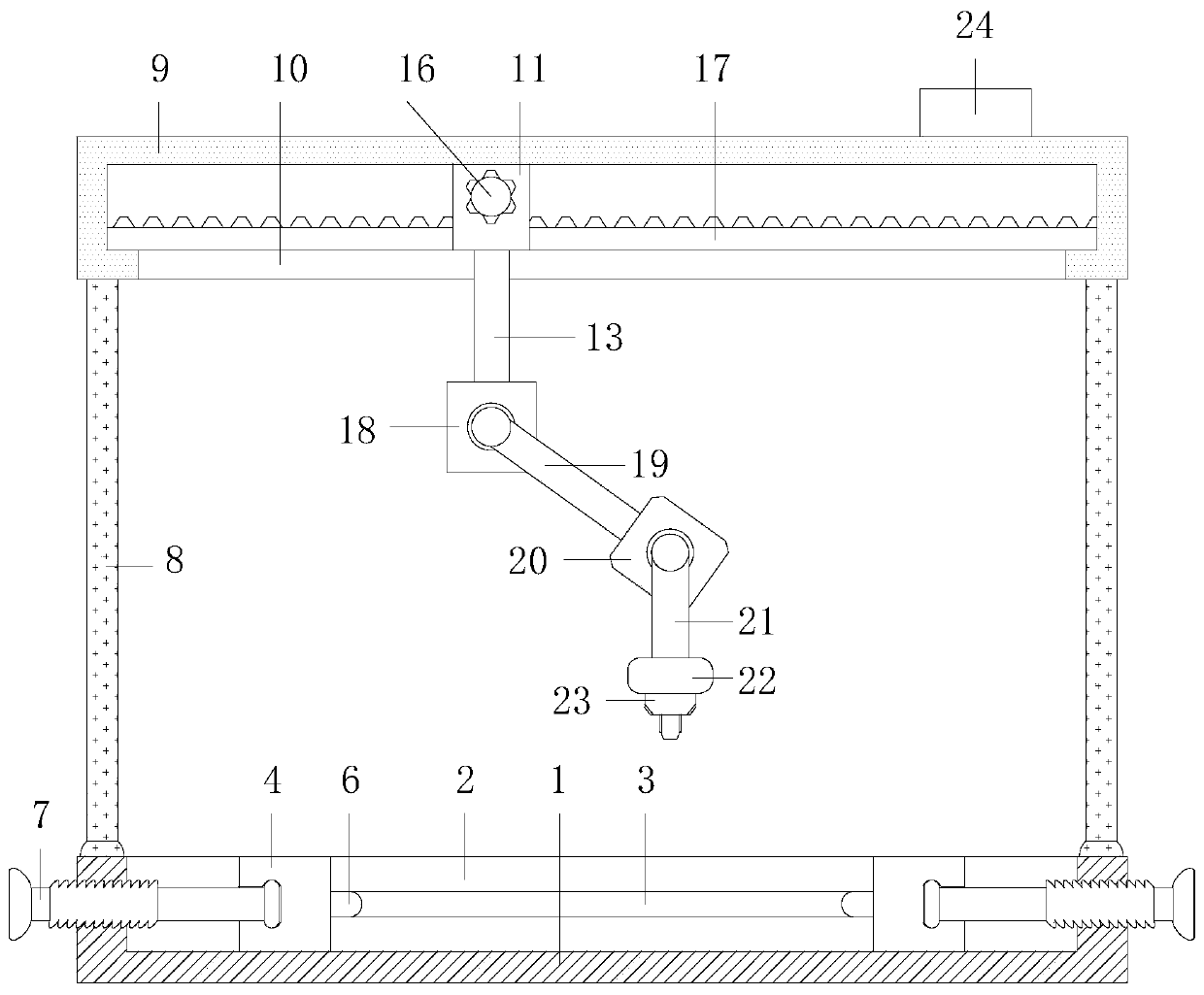
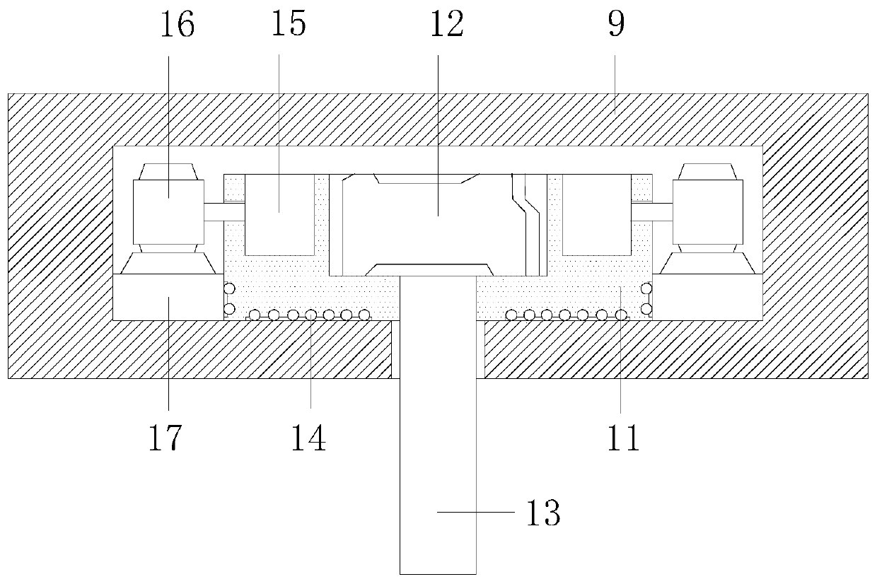
[0028] Specific embodiment 1, according to figure 1 , image 3 and Figure 4 As shown, a laser processing device for PCB boards includes a base 1, a laser generator 22, and a laser gun 23. The base 1 is threadedly connected with a screw 7, and the base 1 supports the screw 7 for rotational movement, and one end of the screw 7 is rotationally connected There is a splint 4, and the screw 7 changes the rotary motion into a linear motion under the conversion of the base 1, and drives the splint 4 to translate. A support seat 9 is installed above the base 1, and the support seat 9 works under the support of the base 1. The support seat 9 is provided with a first reduction motor 12 inside, and the support seat 9 supports the work of the first reduction motor 12, and a connecting rod 13 is connected to the bottom of the first reduction motor 12, and the first reduction motor 12 drives the connecting rod 13 to move, and the first reduction motor 12 Under the non-working state, the c...
specific Embodiment 2
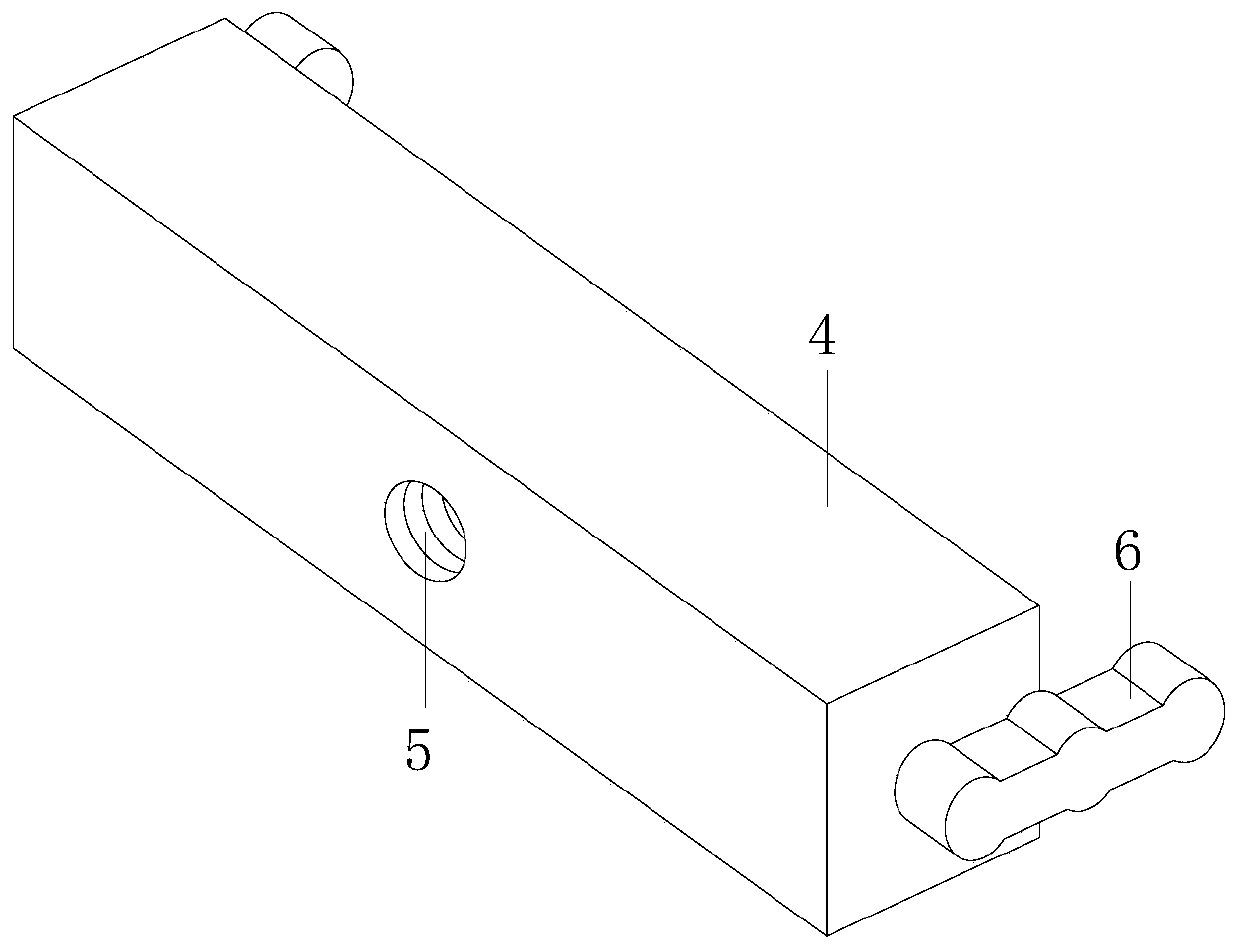
[0029] Specific embodiment 2, with reference to figure 1 and figure 2 , on the basis of specific embodiment 1, screw rod 7 and splint 4 are provided with two groups, conveniently control the fixed position of PCB board, base 1 is processed with chute 2, the surface of splint 4 contacts with the surface of chute 2 smoothly, reduces The wear of the splint 4, at the same time, restricts the movement direction of the splint 4, so that the splint 4 can better maintain the linear motion. The base 1 is processed with a guide groove 3, and the end of the splint 4 is equipped with a guide block 6, and the movement direction of the splint 4 is controlled by the guide block. 6, and the guide block 6 is in point contact with the surface of the guide groove 3, the movement resistance of the guide block 6 is small, the guide block 6 makes the splint 4 move linearly more stably, and the splint 4 is processed with a concave hole for the end of the screw rod 7 Groove 5, at least two pillars ...
specific Embodiment 3
[0030] Specific embodiment 3, with reference to figure 1 and image 3, On the basis of the specific embodiment 1, the support seat 9 is processed with a window 10 for the movement guidance of the connecting rod 13, a part of the connecting rod 13 moves in the window 10, the first reduction motor 12 is embedded in the sliding seat 11, the second A deceleration motor 12 moves with the sliding seat 11, the connecting rod 13 is in clearance fit with the sliding seat 11, the sliding seat 11 is located in the inner cavity of the supporting seat 9, the sliding seat 11 moves in the supporting seat 9, and the sliding seat 11 is set There are a plurality of balls 14, the balls 14 are located below the first reduction motor 12 and the second reduction motor 15, and the longitudinal distribution of the balls 14 is in point contact with the side of the toothed plate 17, reducing the movement resistance of the sliding seat 11, while ensuring that both A toothed plate 17 can limit the direc...
PUM
 Abstract
Description
Claims
Application Information
 - R&D
- Intellectual Property
- Life Sciences
- Materials
- Tech Scout
- Unparalleled Data Quality
- Higher Quality Content
- 60% Fewer Hallucinations
Browse by: Latest US Patents, China's latest patents, Technical Efficacy Thesaurus, Application Domain, Technology Topic, Popular Technical Reports.
© 2025 PatSnap. All rights reserved.Legal|Privacy policy|Modern Slavery Act Transparency Statement|Sitemap|About US| Contact US: help@patsnap.com


