Gas turbine engine rotor disc holding assembly

A technology for gas turbines and rotor disks, applied to engine components, machines/engines, engine manufacturing, etc., can solve problems such as increasing the failure of rotor disks 99, unpopular arch deformation, and reducing the life of rotor disks 99

Active Publication Date: 2020-01-14
SIEMWNS ENERGY GLOBAL GMBH & CO KG
View PDF4 Cites 0 Cited by
  • Summary
  • Abstract
  • Description
  • Claims
  • Application Information

AI Technical Summary

Problems solved by technology

Peak stress concentrations at the edge 93 of the hub 60 in conventionally known rotor disks 99 increase the likelihood of failure of the rotor disk 99 and reduce the life of the rotor disk 99
In addition, arching of the rotor disk 99 is undesirable due to the effect it may have on the position of the turbine buckets during turbine bucket rotation

Method used


Image

  • Gas turbine engine rotor disc holding assembly
  • Gas turbine engine rotor disc holding assembly
  • Gas turbine engine rotor disc holding assembly

Examples


Embodiment Construction

[0029]The above-mentioned and other features of the present technology are described in detail below. The various embodiments are described with reference to the drawings, wherein like reference numerals are used to refer to like elements throughout. In the following description, for purposes of explanation, numerous specific details are set forth in order to provide a thorough understanding of one or more embodiments. It may be noted that the illustrated embodiments are intended to illustrate rather than limit the invention. It is evident that such embodiments may be practiced without these specific details.

[0030] It can be noted that in the present disclosure, terms such as "first" and "second" are used here only to facilitate discussion, and do not have a specific time or sequential meaning unless otherwise indicated.

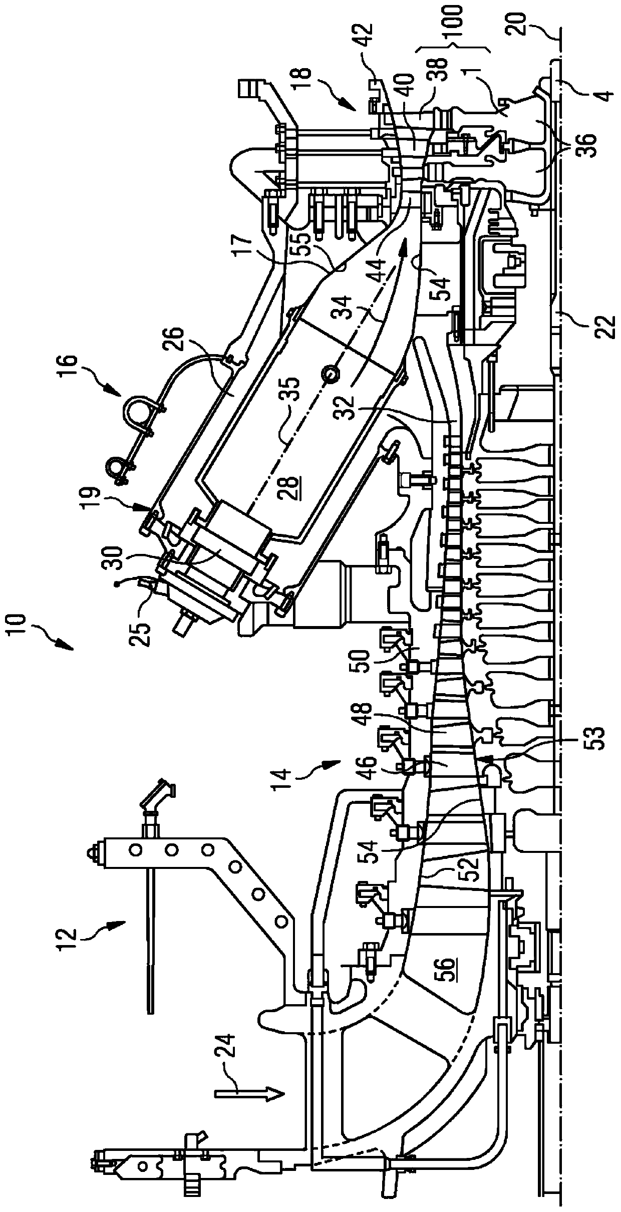
[0031] figure 1 An example of a gas turbine engine 10 is shown in cross-section. Gas turbine engine 10 includes, in flow series, an intake 12, a com...


PUM


Abstract

The invention provides a gas turbine engine rotor disc holding assembly. The assembly comprises a tension bolt and a rotor disc. The rotor disc includes a hub, a web, a blade retention arrangement, arotational axis, a first axial side and a second axial side. The hub has a central bore around the rotational axis. The web is integrally formed with and extends radially outwards from the hub to theblade retention arrangement. The blade retention arrangement has a centre of mass. A radial plane perpendicular to the rotational axis passes through the centre of mass. The first axial side is for engaging the tension bolt. The radial plane intersects the hub defining a first axial side portion towards the first axial side and a second axial side portion towards the second axial side. The secondaxial side portion has an axial extent which is between 10% and 30% greater than an axial extent of the first axial side portion.

Description

technical field [0001] The present invention relates to gas turbine engines, and more particularly, to rotor disks for gas turbine engines. Background technique [0002] The turbine buckets in various modern gas turbine engines are arranged on rotor disks. A plurality of buckets are circumferentially arranged on the rotor disk. The rotor disk has a central hole through which the tensioning bolts pass when the rotor disk is placed in the gas turbine engine together with the circumferentially assembled turbine buckets. The shaft is usually connected to the rotor disc by using a face gear joint or a face gear coupling. When a gas turbine engine is running, an asymmetrical stress distribution is created in such a rotor disk with a central bore and face gear coupling, with peak stresses around the central bore of the hub on the opposite side to which the bolt load is applied. The aforementioned rotor disks and their arrangement within the gas turbine are explained in more deta...

Claims


Application Information

Patent Timeline
Patent Type & Authority Applications(China)
IPC IPC(8): F01D5/02F01D5/06
CPCF05D2250/73F01D5/022F01D5/066F05D2260/941F01D5/02F01D5/06F05D2240/24F01D5/025
Inventor C·基根
Owner SIEMWNS ENERGY GLOBAL GMBH & CO KG
Why Eureka
Try Eureka