
Braking and retarding integration supporting bridge for trailer

A support bridge, integrated technology, applied in the direction of brakes, brake components, brake types, etc., can solve the problems of low degree of integration, difficult installation position of retarder, increased cost, etc., achieve enhanced effect, realize normal circulation and energy The conversion, the effect of reducing the quality of the whole bridge

Active Publication Date: 2020-01-14
BEIJING UNIV OF TECH
View PDF7 Cites 6 Cited by
  • Summary
  • Abstract
  • Description
  • Claims
  • Application Information

AI Technical Summary

Problems solved by technology

But for semi-trailer tractors, the installation position of the retarder is a difficult problem
At present, there are two common methods. One is to install the retarder on the drive train of the trailer. This solution has an obvious braking effect, but the trailer has no braking force. The huge inertia will lead to more serious instability of the whole vehicle.
The other is to install the retarder on the trailer. Since there is no power transmission system, a power bridge is used instead of a support bridge of the trailer, and a retarder is installed on the differential package of the power bridge. This method has a braking effect Although safety and driving safety can be guaranteed, the overall weight has increased significantly. As a module of the vehicle, the retarder needs to be re-matched with the vehicle system. increased, less competitive

Method used


Image

  • Braking and retarding integration supporting bridge for trailer
  • Braking and retarding integration supporting bridge for trailer
  • Braking and retarding integration supporting bridge for trailer

Examples


Embodiment Construction

[0026] In order to make the purpose, technical solutions and advantages of the present invention clearer, the present invention will be further described in detail below in conjunction with the accompanying drawings. The examples given are only for explaining the present invention, not for limiting the scope of the present invention.

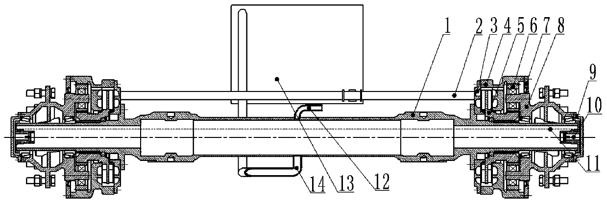
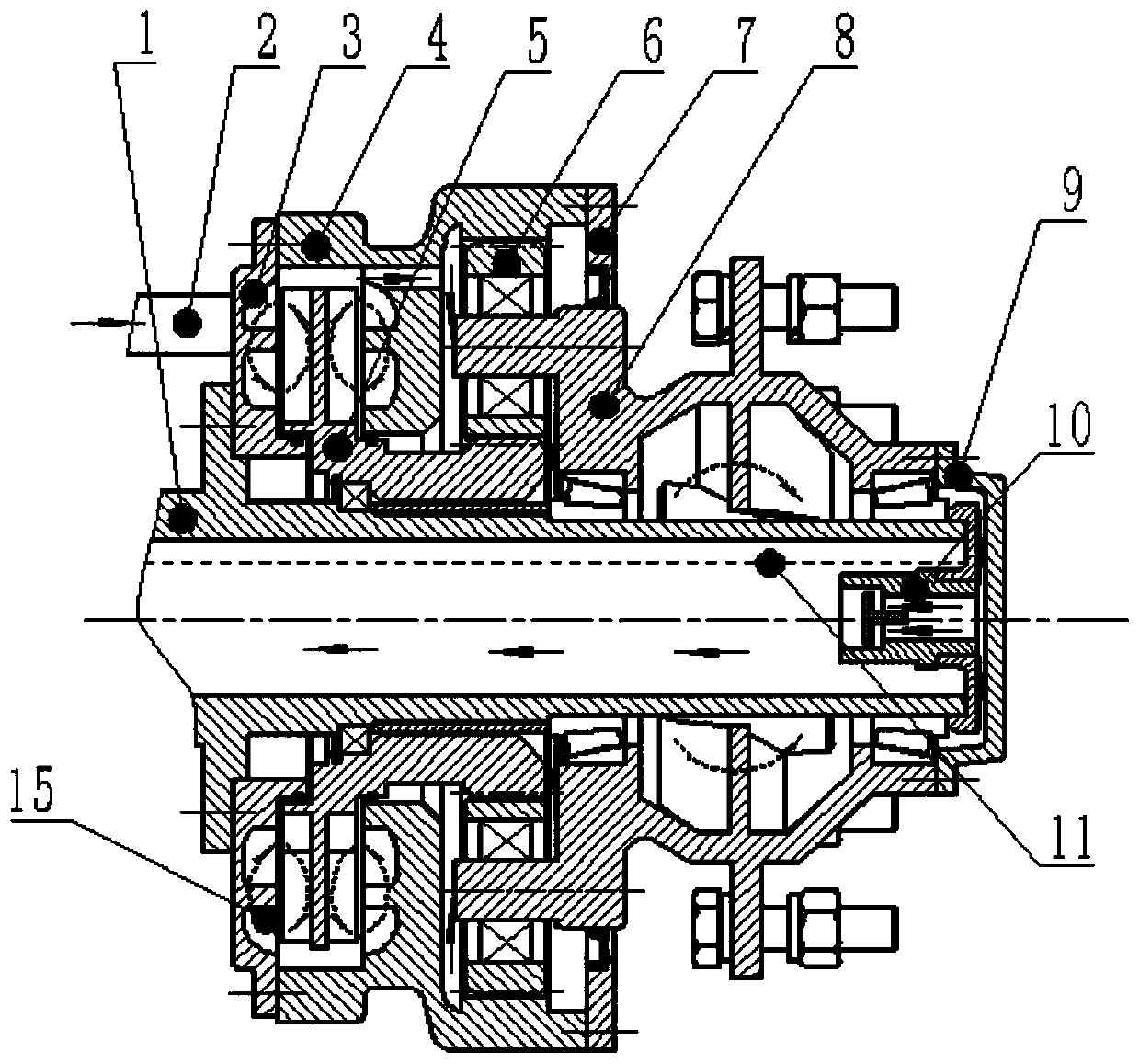
[0027] Such as figure 1 As shown, it is an assembly diagram of a braking and retarding integrated support bridge for a trailer of the present invention, including a support bridge part, a hydraulic retarder part, a speed increasing mechanism part, a heat dissipation circulation system and a control module.

[0028] The supporting bridge part includes a supporting axle housing 1 , a wheel hub 8 and an end cover 9 ;

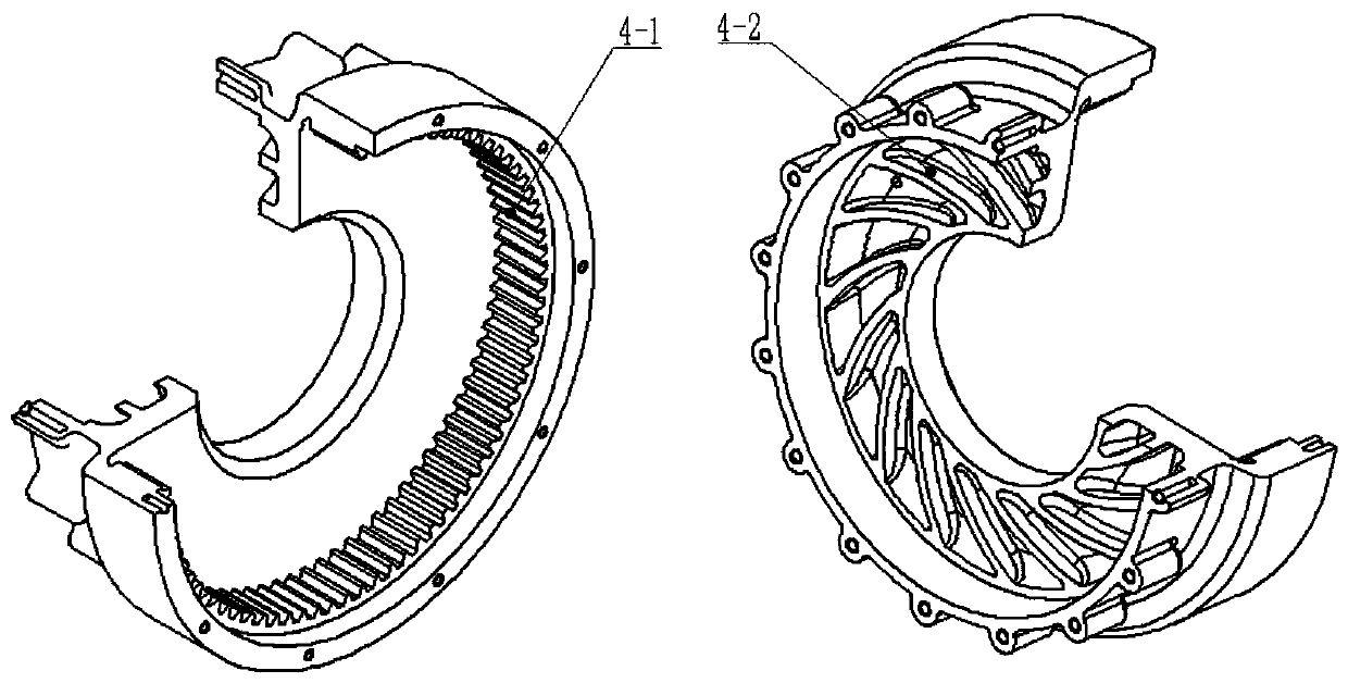
[0029] The hydraulic retarder part includes the left stator impeller 3, the right stator impeller 4-2 and the rotor impeller 5-2, the left stator impeller 3, the right stator impeller 4-2 and the rotor impeller 5-2 are blade structur...


PUM


Abstract

The invention discloses a braking and retarding integration supporting bridge for a trailer. The braking and retarding integration supporting bridge for the trailer comprises a supporting bridge part,a hydrodynamic retarder part, an accelerating mechanism part, a heat dissipation circulating system and a control module. The supporting bridge part comprises supporting bridge housings, hubs and endcovers, the hydrodynamic retarder part comprises left stator impellers, right stator impellers and rotor impellers, and the accelerating mechanism part comprises sun wheels, planet wheels and gear rings. The hydrodynamic retarder is designed at the position of an original braking mechanism, the rotor impellers of retarders and the sun wheels of accelerating mechanisms, the right stator impellersand the gear rings and the hubs and planet carriers are integrally designed, and power is provided for the retarders. A friction braking mechanism and a braking drum are removed from the whole bridge,the weight of the whole bridge is greatly reduced and overally, two modes of braking and retarding of the retarders are controlled by air pressure, adjustment and classification of the moment of force are realized, and the sensitivity of vehicle operation and the driving safety are enhanced.

Description

technical field [0001] The invention belongs to the technical field of automobile auxiliary braking, and in particular relates to a braking and retarding integrated supporting bridge for trailers. Background technique [0002] With the rapid development of the road transportation industry, road transportation has become the main land transportation mode in my country, so heavy trucks and semi-trailer tractors have become the main force of road freight transportation, but with the increase of vehicle load and speed, and Due to the basic conditions of our country's roads - slopes and curves, the load on the braking system of heavy vehicles is increasing, the friction linings of the brakes are severely worn, the brake drums are hot or even burst, and the braking force is insufficient for continuous braking. The semi-trailer tractor is composed of a trailer and a trailer. The transmission system is distributed on the trailer, and the trailer is mainly used to carry the transporte...

Claims


Application Information

Patent Timeline
IPC IPC(8): B60B35/02B60T1/087B60T10/02B60K17/04F16H57/04
CPCB60B35/02B60K17/046B60T1/087B60T10/02F16H57/0413Y02T10/86
Inventor 李德胜高志伟孙耀龙谢立叶乐志
Owner BEIJING UNIV OF TECH
Learn More