
Luminous backlight source of angular thorn circumferential double-connection-surface cathode alternate oblique bow gating structure

A technology of backlight source and cathode, which is applied in cold cathode tube, solid cathode, cold cathode manufacturing and other directions, can solve the problem of unfavorable light-emitting backlight source large cathode current, poor control performance of carbon nanotube cathode, and unfavorable formation of light-emitting backlight source large cathode. current, etc.

Inactive Publication Date: 2020-01-10
JINLING INST OF TECH
View PDF5 Cites 2 Cited by
  • Summary
  • Abstract
  • Description
  • Claims
  • Application Information

AI Technical Summary

Problems solved by technology

[0003] However, there are still some technical difficulties to be solved in the light-emitting backlight with three-pole structure
For example, first, the electron emission efficiency of the carbon nanotube cathode is very low
Among the prepared carbon nanotube cathodes, some carbon nanotubes can emit more electrons, some carbon nanotubes can only emit less electrons, and even a considerable part of carbon nanotubes do not emit electrons at all. , so generally speaking, the electron emission efficiency of the carbon nanotube cathode is very low, and it is also very unfavorable to form a large cathode current of the luminescent backlight
Second, the control performance of the gate voltage on the carbon nanotube cathode is very poor
Third, the fabrication area of ​​the carbon nanotube cathode is very small
The manufacturing area of ​​the carbon nanotube cathode is small, that is to say, the number of carbon nanotubes is reduced, which is very unfavorable for forming a large cathode current of a luminescent backlight

Method used


Image

  • Luminous backlight source of angular thorn circumferential double-connection-surface cathode alternate oblique bow gating structure
  • Luminous backlight source of angular thorn circumferential double-connection-surface cathode alternate oblique bow gating structure
  • Luminous backlight source of angular thorn circumferential double-connection-surface cathode alternate oblique bow gating structure

Examples


Embodiment Construction

[0050] The present invention will be further described below in conjunction with the accompanying drawings and embodiments, but the present invention is not limited to this embodiment.

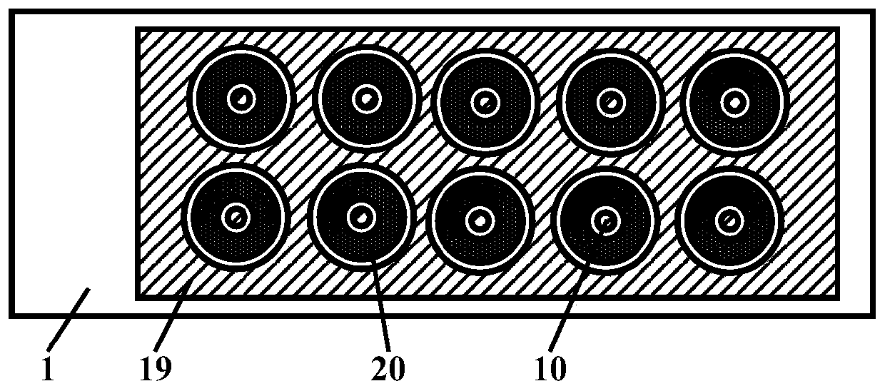
[0051] In this embodiment, the luminescent backlight of the double-connected surface cathode alternating oblique arch gating structure around the horn thorn ring is as follows: figure 1 , figure 2 and image 3 As shown, it includes a vacuum enclosure and a getter 25 accessory components located in the vacuum enclosure; the vacuum enclosure is composed of a front transparent hard glass plate 21, a rear transparent hard glass plate 1 and a glass narrow frame strip 26; the front transparent On the hard glass plate, there are anode pad film conduction layer 22, anode gray silver connection layer 23 and thin luminescent layer 24, and described anode pad film conduction layer is connected with anode gray silver connection layer, and described thin luminescence layer It is made on the conductive l...


PUM


Abstract

The invention discloses a luminous backlight source of an angular thorn circumferential double-connection-surface cathode alternate oblique bow gating structure. The backlight source comprises a vacuum sealing body and a getter accessory component located in the vacuum sealing body. The vacuum sealing body is composed of a front transparent hard glass plate, a rear transparent hard glass plate anda narrow glass frame strip. An anode pad film conduction layer, an anode gray silver-connected electric layer and a thin light-emitting layer are arranged on the front transparent hard glass plate. The anode pad film conduction layer is connected with the anode gray silver-connected electric layer, and the thin light-emitting layer is manufactured on the anode pad film conduction layer. The reartransparent hard glass plate is provided with an angular thorn circumferential double-connection-surface cathode alternate oblique bow gating structure. The luminous backlight source has advantages that a manufactured structure is simple, light-emitting brightness of the luminous backlight source is high and light-emitting gray scale adjustable performance of the luminous backlight source is excellent.

Description

technical field [0001] The present invention belongs to the fields of plane display technology, nanometer science and technology, integrated circuit science and technology, microelectronic science and technology, optoelectronic science and technology, semiconductor science and technology, and vacuum science and technology. The invention relates to the production of a planar luminous backlight, specifically to the production of a carbon nanotube cathode, in particular to a luminous backlight with a double-connected surface cathode alternate oblique arch gating structure around the horn thorn ring and its manufacturing process. Background technique [0002] In a suitable vacuum environment, carbon nanotubes can emit electrons, which makes carbon nanotubes a very suitable cathode material. With the large-scale promotion of the screen printing process, it is easy to make large-area, patterned carbon nanotube cathodes, which also accelerates the production process of carbon nanot...

Claims


Application Information

Patent Timeline
Patent Type & Authority Applications(China)
IPC IPC(8): H01J17/06H01J17/04H01J17/12H01J17/38H01J17/48H01J9/02H01J9/20
CPCH01J9/02H01J9/025H01J9/20H01J17/04H01J17/066H01J17/12H01J17/38H01J17/48
Inventor 李玉魁
Owner JINLING INST OF TECH
Learn More