Eureka AIR delivers breakthrough ideas for toughest innovation challenges, trusted by R&D personnel around the world.

Method and device for generating pulse compression coefficient of target detection radar system

A technology of pulse compression coefficient and radar system, which is applied in the direction of measuring device, radio wave measurement system, radio wave reflection/re-radiation, etc., can solve the problem of inaccurate pulse compression coefficient, pulse compression coefficient not comprehensively considered, and failure to meet the working conditions and other issues, to achieve the effect of improving pulse compression performance and high radar distance resolution

Active Publication Date: 2020-01-10
成都汇蓉国科微系统技术有限公司
View PDF6 Cites 2 Cited by
  • Summary
  • Abstract
  • Description
  • Claims
  • Application Information

AI Technical Summary

Problems solved by technology

[0006] In order to solve the above-mentioned technical problems, the present invention proposes a method and device for generating a pulse compression coefficient of a target detection radar system. Inaccurate, technical problems that cannot meet the actual working situation

Method used


Image

  • Method and device for generating pulse compression coefficient of target detection radar system
  • Method and device for generating pulse compression coefficient of target detection radar system
  • Method and device for generating pulse compression coefficient of target detection radar system

Examples


Embodiment Construction

[0048] In order to make the purpose, technical solution and advantages of the present invention clearer, the technical solution of the present invention will be clearly and completely described below in conjunction with specific embodiments of the present invention and corresponding drawings. Apparently, the described embodiments are only some of the embodiments of the present invention, but not all of them. Based on the embodiments of the present invention, all other embodiments obtained by persons of ordinary skill in the art without making creative efforts belong to the protection scope of the present invention.

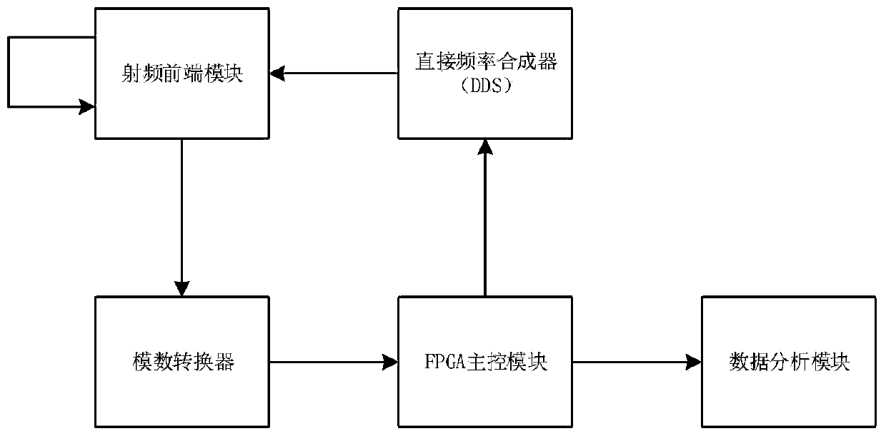
[0049] combine first figure 1 Illustrate the overall architecture of the pulse compression coefficient generation device for realizing the target detection radar system of the present invention, figure 1 A general architecture diagram of a device for generating a pulse compression coefficient of a target detection radar system according to an embodiment of the pr...


PUM


Abstract

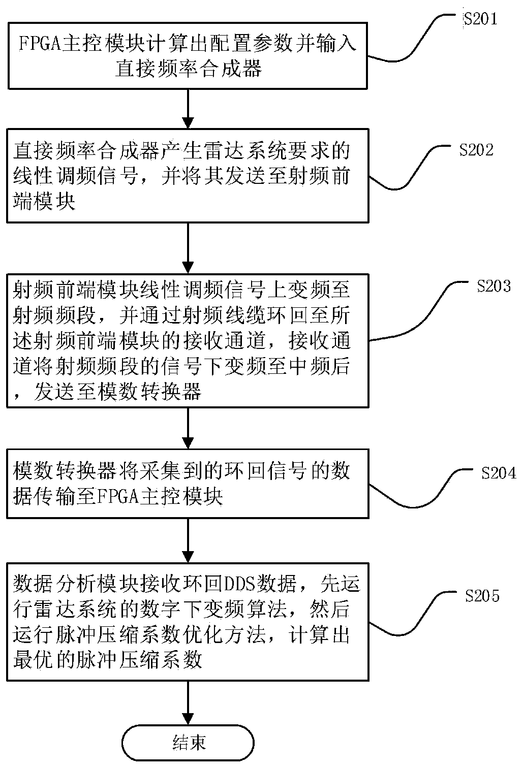
The invention provides a method and device for generating the pulse compression coefficient of a target detection radar system. The method comprises the following steps of calculating configuration parameters by an FPGA main control module, and inputting the configuration parameters into a direct frequency synthesizer; generating linear frequency modulation signals required by the radar system through the direct frequency synthesizer, and sending the linear frequency modulation signals to a radio frequency front-end module; performing up-conversion on the linear frequency modulation signals byan emitting channel of the radio frequency front-end module to be in a radio frequency band; looping back radio frequency cables to a receiving channel of the radio frequency front-end module; performing down-conversion on the signals at the radio frequency band by the receiving channel to be at the medium frequency, and sending the signals to an analog-digital converter; transmitting data of loopback signals to the FPGA main control module by the analog-digital converter; receiving loopback DDS data exported by the FPGA main control module by a data analysis module; and calculating the optimal pulse compression coefficient by a pulse compression coefficient optimization method. According to the scheme, the pulse compression performance of the radar system can be improved; and higher radar range resolution is obtained.

Description

technical field [0001] The invention relates to the field of radar system detection, in particular to a method and device for generating a pulse compression coefficient of a target detection radar system, and in particular to a method and device for generating a pulse compression coefficient for a low-small-slow target detection radar system. Background technique [0002] At present, the development of low, small and slow targets such as unmanned aerial vehicles is getting faster and faster, and more and more low and slow targets are put into military and civil applications. The effective detection of such small and slow targets is an urgent problem to be solved in the current national defense security and information security. [0003] In order to obtain high distance detection accuracy, the radar system needs to emit pulses with a sufficiently narrow width. In addition, in order to detect long-distance targets, the radar system must emit a signal with high energy. However...

Claims


Application Information

Patent Timeline
Patent Type & Authority Applications(China)
IPC IPC(8): G01S13/88
CPCG01S13/88
Inventor 胥秋冷立根汪晓青王飞
Owner 成都汇蓉国科微系统技术有限公司
Why Eureka
Eureka Blog
Learn More