
Hub detection device

A detection device and wheel hub technology, applied in the field of automation, can solve problems such as difficulty in ensuring consistent feeding positions, affecting product quality, and large manual operation deviation, so as to reduce incomplete detection, high accuracy of judgment results, and convenient operation. Effect

Active Publication Date: 2020-01-10
苏州工业园区道青科技有限公司
View PDF12 Cites 2 Cited by
  • Summary
  • Abstract
  • Description
  • Claims
  • Application Information

AI Technical Summary

Problems solved by technology

[0003] At present, it is necessary to detect the defects of the wheel hub. The traditional method is mainly manual operation, which is relatively cumbersome, and because the detection of the wheel hub needs to be rotated at multiple angles, if manual operation is also used, it will be quite troublesome, and the test results are not accurate. Manual operation The deviation is large, and some places may not be detected, which will affect the quality of the product when it leaves the factory; if the loading process of the wheel hub is manually operated, it will not only be inefficient, but also difficult to ensure consistent feeding positions, which will also affect the test results; therefore, In order to ensure that the hub detection is in place and the results are accurate, and to improve the detection efficiency, we have designed an automated hub detection device to solve the problem

Method used


Image

  • Hub detection device
  • Hub detection device
  • Hub detection device

Examples


Embodiment

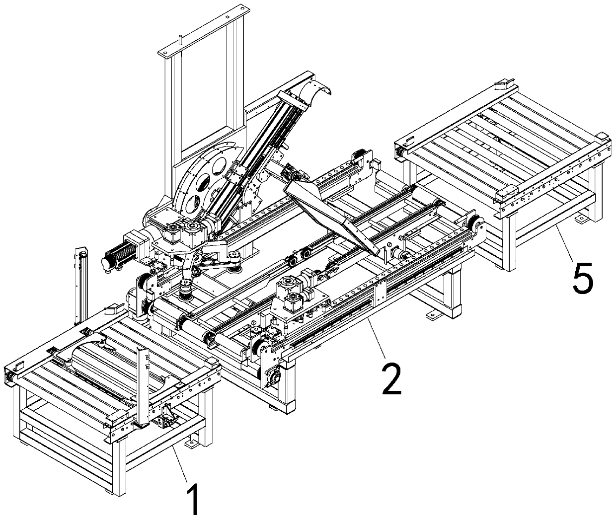
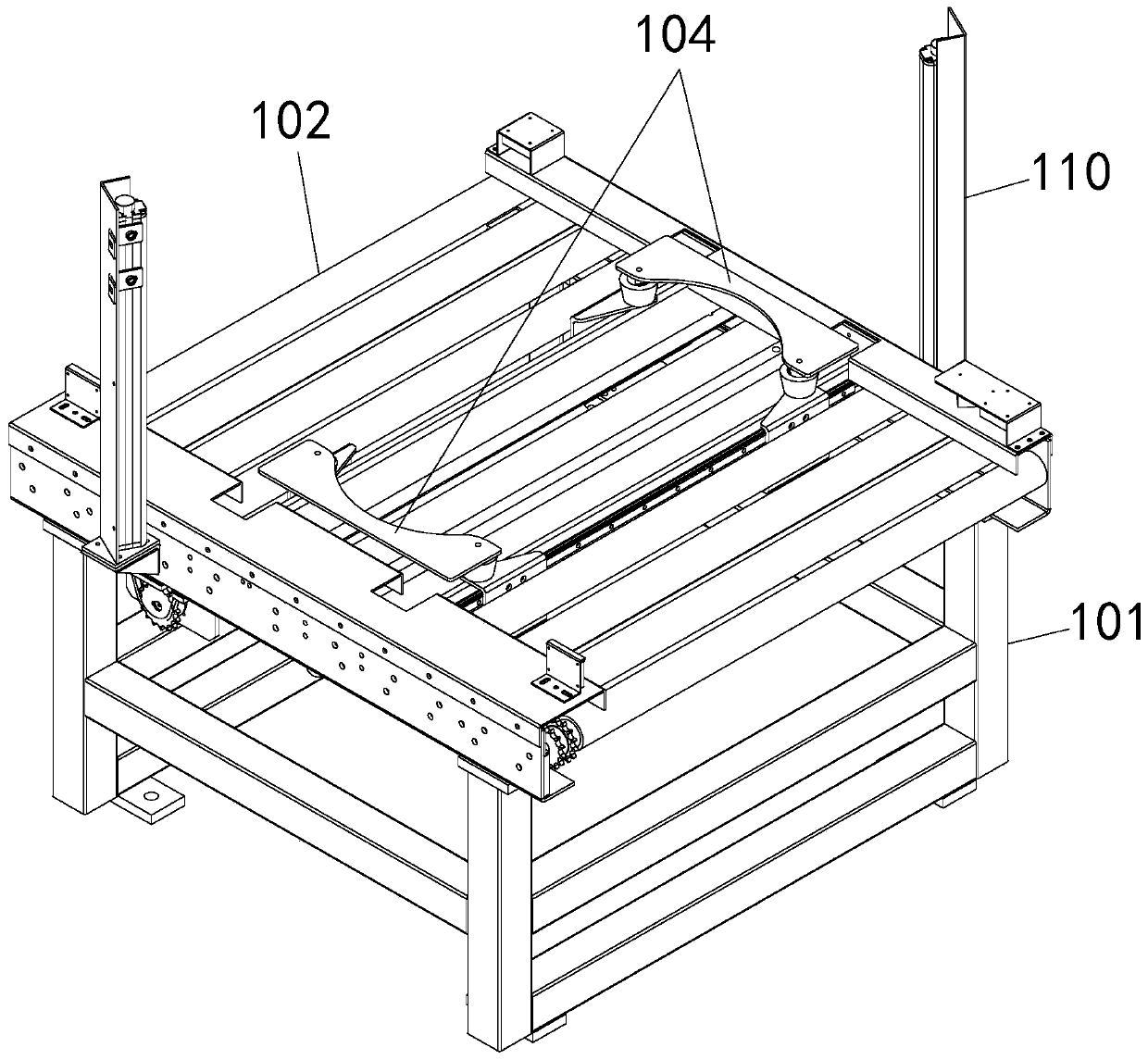
[0042] Example: such as figure 1 ~ Figure 14 As shown, a wheel hub detection device includes a feeding centering mechanism 1, a wheel hub detecting mechanism 2, and a discharge conveying mechanism 5 arranged in sequence; the feeding centering mechanism 1 includes a first support frame 101, and above the first support frame 101 A first assembly line 102 is provided, and two parallel first guide rails 103 are arranged on the first assembly line 102, and the first guide rail 103 is arranged perpendicular to the transmission direction of the first assembly line 102; the first assembly line 102 is provided with a For the symmetrical first clamping assembly 104, the first clamping assembly 104 includes a first moving plate 1041 at the lower end, and the two ends of the first moving plate 1041 are horizontally moved and arranged on the first guide rail 103, above the first moving plate 1041 A first arc-shaped plate 1042 for clamping the wheel hub is provided, the arc side of the f...


PUM


Abstract

The invention discloses a hub detection device. The hub detection device comprises a feeding-centering mechanism, a hub detection mechanism and a discharging-conveying mechanism which are arranged insequence, wherein the hub detection mechanism comprises a position adjustment mechanism for a ray emitter. The feeding-centering mechanism is used for centering a hub on an assembly line, so that thehub is positioned at the center position of the assembly line after entering the detection mechanism, and the stability of the hub feeding position is ensured. The hub detection mechanism is used forrealizing automatic clamping and rotation of the hub on the assembly line. The position adjustment mechanism is used for realizing defect detection of the hub. The multi-directional detection of the hub is realized by realizing the swinging of the ray emitter, so that high detection efficiency and wide detection range are achieved. A calibration mechanism is used for observing the definition of pinhole imaging by irradiation of steps of different thicknesses through the ray emitter in order to judge whether the ray emitter needs to be adjusted or not, so that the judgement result is high in accuracy; the situation of insufficient detection is reduced; and the detection accuracy of the ray emitter is ensured.

Description

technical field [0001] The invention belongs to the technical field of automation, and in particular relates to a wheel hub detection device. Background technique [0002] The wheel hub is a barrel-shaped metal part with the center mounted on the shaft that supports the tire inner profile. [0003] At present, it is necessary to detect the defects of the wheel hub. The traditional method is mainly manual operation, which is relatively cumbersome, and because the detection of the wheel hub needs to be rotated at multiple angles, if manual operation is also used, it will be quite troublesome, and the test results are not accurate. Manual operation The deviation is large, and some places may not be detected, which will affect the quality of the product when it leaves the factory; if the loading process of the wheel hub is manually operated, it will not only be inefficient, but also difficult to ensure consistent feeding positions, which will also affect the test results; theref...

Claims


Application Information

Patent Timeline
IPC IPC(8): G01N23/04B65G47/90B23P21/00
CPCG01N23/04B65G47/902B23P21/00G01N2223/03G01N2223/624G01N2223/646
Inventor 陶维道刘军张福旺王庆涛周冰黄伟博徐刘龙
Owner 苏州工业园区道青科技有限公司
Learn More