
Laser turning device, laser processing light path system and light path debugging method

A laser processing and optical path system technology, applied in laser welding equipment, metal processing equipment, manufacturing tools, etc., can solve the problems of equipment space structure limitation, easy change of moving mechanism, poor stability, etc., and achieve a simple method of optical path debugging. , The effect of fast and convenient beam expansion and high debugging accuracy

Active Publication Date: 2020-01-10
BEIJING SEMICON EQUIP INST THE 45TH RES INST OF CETC
View PDF16 Cites 1 Cited by
  • Summary
  • Abstract
  • Description
  • Claims
  • Application Information

AI Technical Summary

Problems solved by technology

However, when applied to industrial production equipment, affected by factors such as ambient temperature and motor vibration, the moving mechanism of the adjustment seat is prone to change and the stability is not good.
In addition, limited by the space structure of the equipment, the installation method of the standard purchased optical adjustment seat is not flexible, which is not conducive to equipment integration

Method used


Image

  • Laser turning device, laser processing light path system and light path debugging method
  • Laser turning device, laser processing light path system and light path debugging method
  • Laser turning device, laser processing light path system and light path debugging method

Examples


Embodiment Construction

[0039] In order to make the purposes, technical solutions and advantages of the embodiments of the present application clearer, the technical solutions in the embodiments of the present application will be clearly and completely described below in conjunction with the drawings in the embodiments of the present application. Obviously, the described embodiments It is a part of the embodiments of this application, not all of them. The components of the embodiments of the application generally described and illustrated in the figures herein may be arranged and designed in a variety of different configurations.

[0040] Accordingly, the following detailed description of the embodiments of the application provided in the accompanying drawings is not intended to limit the scope of the claimed application, but merely represents selected embodiments of the application. Based on the embodiments in this application, all other embodiments obtained by persons of ordinary skill in the art w...


PUM


Abstract

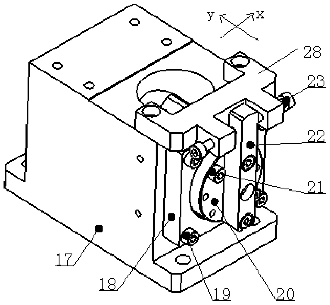
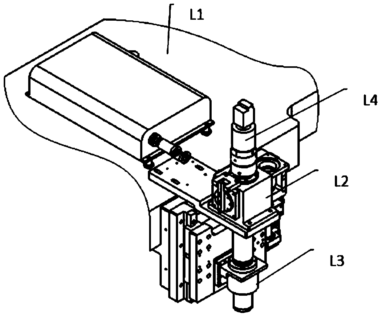
The invention discloses a laser turning device, a laser processing light path system and a light path debugging method, and relates to the technical field of laser processing. The laser processing light path system comprises a processing base, a laser beam expansion and collimation device, a laser turning device, a laser focusing device and a coaxial regulation device. The laser beam expansion andcollimation device and the laser turning device are arranged in a spaced manner in the X-axis direction. The laser beam expansion and collimation device is used for emitting a laser and conducting collimation and beam expansion on the laser. The laser focusing device is connected to the processing base. The laser focusing device is used for focusing the laser, emitted out from a light path outlet, into a fine light spot used for processing. The coaxial regulation device is connected to the laser turning device in the Z-axis direction and is used for recognizing an opposite-position processingmark and assisting in regulating the laser light path. By means of the laser processing light path system, beam expansion, turning regulation and focusing of a laser beam can be rapidly and conveniently achieved, the light path debugging method is simple and high in debugging precision, and guarantee is provided for industrialized production of laser processing devices.

Description

technical field [0001] The present application relates to the technical field of laser processing, in particular, to a laser turning device, a laser processing optical path system and an optical path debugging method. Background technique [0002] With the development of laser processing technology and the expansion of application fields, the consistency and stability of laser processing equipment have higher requirements. The laser optical path system is the core functional part of the equipment. It needs to be considered comprehensively in terms of structural design and debugging methods to obtain a focused spot with uniform energy and shape distribution to achieve excellent processing quality. [0003] The existing multi-dimensional angle optical adjustment seat is generally used in laboratories and is easy to adjust. However, when applied to industrial production equipment, affected by factors such as ambient temperature and motor vibration, the moving mechanism of the ...

Claims


Application Information

Patent Timeline
Patent Type & Authority Applications(China)
IPC IPC(8): B23K26/046B23K26/064
CPCB23K26/046B23K26/064
Inventor 高爱梅李星辰武震郑佳晶
Owner BEIJING SEMICON EQUIP INST THE 45TH RES INST OF CETC
Learn More