Duplexer, multiplexer, high-frequency front-end circuit and communication device
A technology of duplexer and multiplexer, applied in high-frequency front-end circuits and communication devices, duplexers, and multiplexers, can solve the problems of low impedance at Fs frequency, complex impedance characteristics of FBAR, and high impedance at Fp frequency , to achieve the effect of improving roll-off, high roll-off and out-of-band suppression
- Summary
- Abstract
- Description
- Claims
- Application Information
AI Technical Summary
Problems solved by technology
Method used
Image

Examples
Embodiment 1
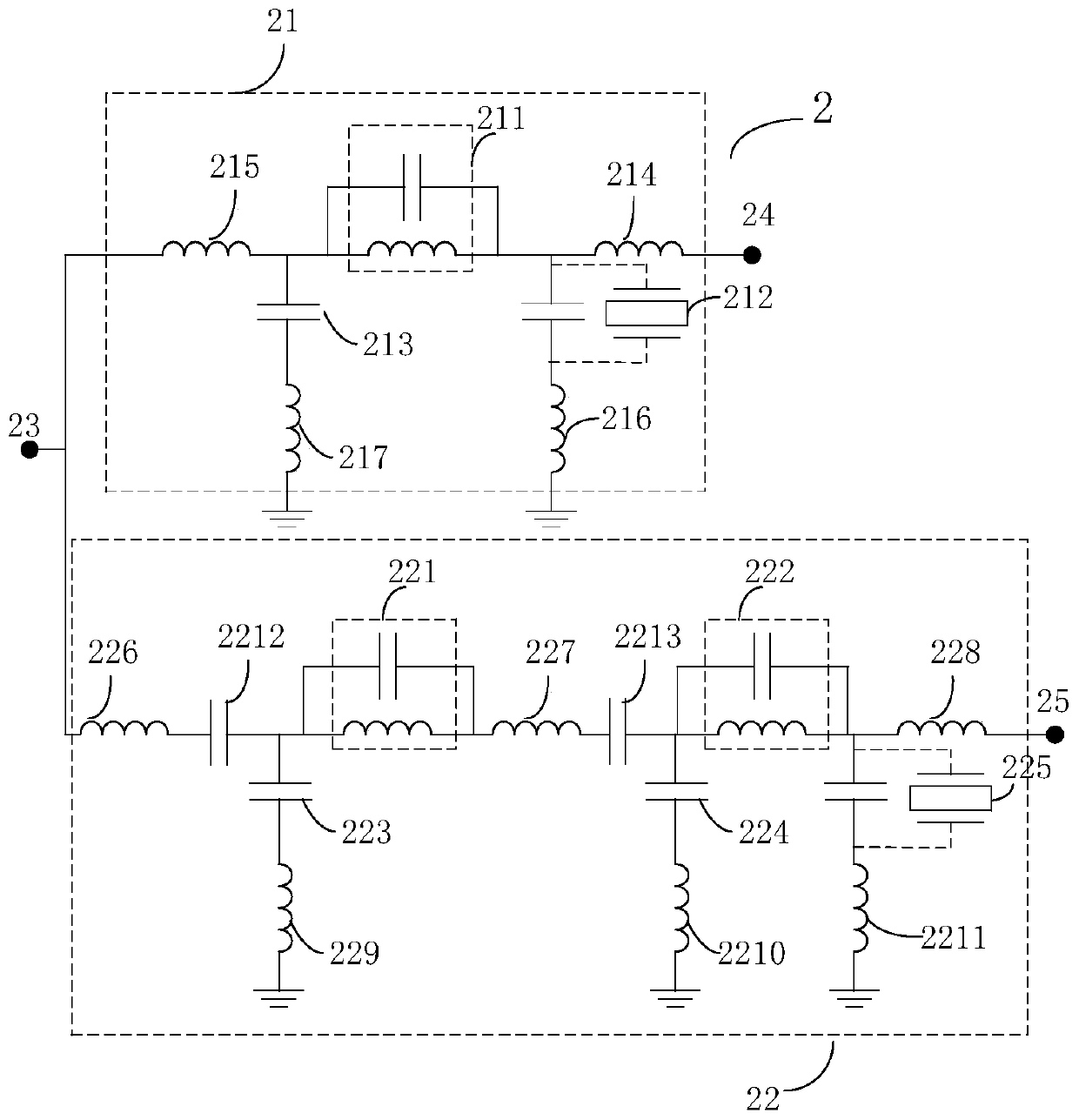
[0069] figure 2 It is a circuit configuration diagram of the duplexer 2 according to the embodiment. Such as figure 2 As shown, the duplexer 2 includes a transmit side filter 21 , a receive side filter 22 and an antenna terminal 23 .
[0070] The transmission side filter 21 receives a transmission wave generated by a transmission circuit through a transmission input terminal 24, filters the transmission wave in a transmission pass band, and outputs it to the antenna terminal 23 which is a transmission side output terminal. More specifically, the transmitting side filter 21 includes an LC resonance unit 211 , a resonator 212 , a capacitor 213 , matching inductance elements 214 to 217 and a transmitting input terminal 24 .
[0071] The LC resonance unit 211 is connected between the transmission input terminal 24 and the antenna terminal 23; the resonator 212 is connected between the transmission input terminal 24 and the reference terminal (ground), and the capacitor 213 is ...
Embodiment 2
[0082] Figure 9 It is a circuit configuration diagram of the duplexer 3 according to the embodiment. Such as Figure 9 As shown, the duplexer 3 includes a transmitting filter 31 , a receiving filter 32 and an antenna terminal 33 .
[0083] The transmission side filter 31 receives a transmission wave generated by a transmission circuit through a transmission input terminal 34, filters the transmission wave in a transmission pass band, and outputs it to the antenna terminal 33 which is a transmission side output terminal. More specifically, the transmitting side filter 31 includes an LC resonance unit 311 , resonators 312 - 313 , a capacitor 314 , matching inductance elements 315 - 318 and a transmitting input terminal 34 .
[0084] The LC resonance unit 311 is connected between the transmission input terminal 34 and the antenna terminal 33; the resonators 312-313 are connected in parallel between the transmission input terminal 34 and the reference terminal (ground), and the...
Embodiment 3
[0092] Figure 10 It is a circuit configuration diagram of the duplexer 4 according to the embodiment. Such as Figure 10 As shown, the duplexer 4 includes a transmitting filter 41 , a receiving filter 42 and an antenna terminal 43 .
[0093] The transmission side filter 41 receives a transmission wave generated by a transmission circuit through a transmission input terminal 44, filters the transmission wave in a transmission pass band, and outputs it to the antenna terminal 43 which is a transmission side output terminal. More specifically, the transmission-side filter 41 includes resonators 411 to 412 , a capacitor 413 , inductance elements 414 to 418 for matching, and a transmission input terminal 44 .
[0094] The resonator 411 is connected between the transmission input terminal 44 and the antenna terminal 43, the resonator 412 is connected between the transmission input terminal 44 and the reference terminal (ground), and the capacitor 413 is connected between the antenn...
PUM
 Abstract
Description
Claims
Application Information
 - R&D
- Intellectual Property
- Life Sciences
- Materials
- Tech Scout
- Unparalleled Data Quality
- Higher Quality Content
- 60% Fewer Hallucinations
Browse by: Latest US Patents, China's latest patents, Technical Efficacy Thesaurus, Application Domain, Technology Topic, Popular Technical Reports.
© 2025 PatSnap. All rights reserved.Legal|Privacy policy|Modern Slavery Act Transparency Statement|Sitemap|About US| Contact US: help@patsnap.com