Hanging belt conveyer

A belt conveyor and hanging technology, applied in the direction of conveyor, conveyor objects, transportation and packaging, can solve the problems of narrow space, high construction cost, low installation and disassembly efficiency, etc. The effect of construction efficiency and convenient movement and adjustment

Pending Publication Date: 2020-01-07
JIAOZUO CREATION HEAVY IND CO LTD
View PDF1 Cites 2 Cited by
  • Summary
  • Abstract
  • Description
  • Claims
  • Application Information

AI Technical Summary

Problems solved by technology

[0002] When erecting a traditional belt conveyor, it is necessary to lay the foundation and install parts one by one. The whole process requires a lot of labor and time.
However, in underground mining roadway, tunnel excavation and other projects, there are factors such as narrow space and difficulty in ground foundation laying. The traditional belt conveyor has low installation and disassembly efficiency and high construction cost, which can no longer meet the needs of actual work.

Method used


Image

  • Hanging belt conveyer
  • Hanging belt conveyer
  • Hanging belt conveyer

Examples


Embodiment 1

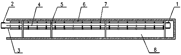
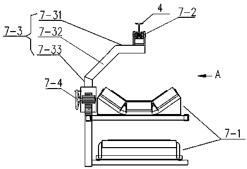
[0023] Such as figure 1 and Figure 3~6 As shown, the present invention provides a hanging belt conveyor, comprising a nose 1, a tail 2 and a conveyor belt 3, the conveyor belt 3 is connected to the nose 1 and the tail 2, and also includes a main beam 4 , support beam 5, connecting rod assembly 6 and hanging unit 7, the main beam 4 is an I-shaped steel structure, the hanging unit 7 is provided with multiple groups, and the hanging unit 7 is rollingly connected on the main beam 4 , the connecting rod assembly 6 is horizontally connected between two adjacent groups of suspension units 7, the main beam 4 is suspended in the roadway 8 through a plurality of supporting beams 5, and the nose 1 and the tail 2 are respectively Correspondingly arranged at both ends of the main beam 4, and the main beam 4 is correspondingly arranged above the centerline of the conveyor belt 3, and the hanging unit 7 is provided with a set of idlers 7-1, and the set of idlers 7-1 supports Below the con...

Embodiment 2

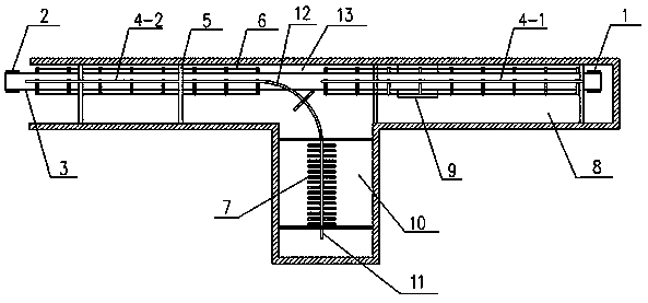
[0028] Such as figure 2 As shown in ~ 6, the present invention provides a kind of hanging belt type conveyor, comprises machine head 1, machine tail 2, conveyer belt 3, assembly storehouse 10 and storage belt device 9, and described conveyer belt 3 is connected on machine head 1 And on the tail 2, it also includes a main beam 4, a support beam 5, a connecting rod assembly 6 and a suspension unit 7, the suspension unit 7 is provided with multiple groups, and the support beam 5 is arranged at two sides of the roadway 8 at intervals. On the side and side walls, the top of the main beam 4 is connected to the support beam 5, the suspension unit 7 is rollingly connected to the main beam 4, and the connecting rod assembly 6 is horizontally connected to two adjacent groups of suspension units 7. Between, the head 1 and the tail 2 are respectively arranged at the two ends of the main beam 4, and the main beam 4 is correspondingly arranged above the center line of the conveyor belt 3, ...


PUM


Abstract

The invention belongs to the technical field of conveying devices, and specifically relates to a hanging belt conveyer. The hanging belt conveyer comprises a machine head, a machine tail and a conveying belt, wherein the conveying belt is connected to the machine head and the machine tail. The hanging belt conveyer further comprises a main beam, support beams, connection rod assemblies and hangingunits, wherein the main beam is of an I-shaped steel structure; a plurality of groups of the hanging units are arranged, and connected to the main beam in a rolling manner; one connection rod assembly is horizontally connected between each two adjacent groups of the hanging units; the main beam is suspended in a tunnel or a roadway via a plurality of the support beams; the machine head and the machine tail are correspondingly arranged at the two ends of the main beam separately, and the main beam is correspondingly arranged above the central line of the conveying belt; a carrier roller groupis arranged on the hanging unit; and the carrier roller group is supported below the conveying belt. The hanging belt conveyer has the following beneficial effects: the device is simple in structure,suitable for modularized production and machining, low in construction cost, and good in installation and detachment effect; and the equipment is capable of being repeatedly used, and suitable for material conveying working in underground roadway mining, tunnel driving and other engineering.

Description

technical field [0001] The invention belongs to the technical field of conveying devices, and in particular relates to a hanging belt conveyor. Background technique [0002] When erecting a traditional belt conveyor, it is necessary to lay the foundation and install parts one by one. The whole process requires a lot of labor and time. However, in underground mining roadway, tunnel excavation and other projects, there are factors such as narrow space and difficulty in ground foundation laying. The traditional belt conveyor has low installation and disassembly efficiency and high construction cost, which can no longer meet the needs of actual work. [0003] For this reason, there is an urgent need for a new type of belt conveyor with a novel structure, suitable for underground mining roadways, tunnel excavation and other projects, so as to reduce construction costs and improve installation and disassembly efficiency. Contents of the invention [0004] In order to solve the ...

Claims


Application Information

Patent Timeline
Patent Type & Authority Applications(China)
IPC IPC(8): B65G41/00B65G21/02
CPCB65G21/02B65G41/00
Inventor 孟凡波宋志杰冯智文王汉生石宝中曲高飞
Owner JIAOZUO CREATION HEAVY IND CO LTD
Why Eureka
Try Eureka