
A mandibular anterior teeth anchorage device for orthodontics

A technology of mandibular and anterior teeth is applied in the field of mandibular anterior teeth anchorage device, which can solve the problems of large periodontal reserve force of anterior and posterior teeth, and can not achieve clinical mandibular anterior teeth anchorage, etc., so as to shorten the treatment time and save money. The effect of chairside operation time and improving the success rate

Active Publication Date: 2021-06-01
祝东波
View PDF5 Cites 1 Cited by
  • Summary
  • Abstract
  • Description
  • Claims
  • Application Information

AI Technical Summary

Problems solved by technology

[0003] The traditional mandibular anterior teeth anchorage (commonly known as resistance) often shows that the six anterior teeth of the mandible are carried out on the brackets equipped with orthodontic appliances, and the "8" ligation method is performed with orthodontic ligature wire as the mandibular anterior teeth. 0.8mm stainless steel wire is also used to bend the auxiliary arch, and the ligature wire is fixed on the mandibular appliance to further enhance the anchorage of the mandibular anterior teeth; these two devices cannot achieve clinical mandibular alignment well in clinical orthodontics. The anchorage of the anterior teeth is always pulled backward by the strong pulling force of the posterior teeth—the reaction force, which brings a lot of trouble and inconvenience to the clinicians. Because of the large difference in the periodontal reserve force of the anterior and posterior teeth during orthodontic treatment, How to use the weak mandibular anterior teeth combined anchorage device to complete the clinical traction of the mandibular posterior teeth to move forward is very urgent

Method used


Image

  • A mandibular anterior teeth anchorage device for orthodontics

Examples


Embodiment Construction

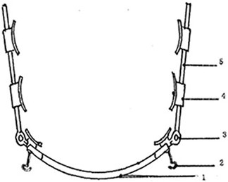
[0019] With reference to the accompanying drawings, the mandibular anterior tooth anchorage device designed for orthodontics is composed of a main rod 1, a traction hook 2, a joint 3, a bracket with a tube 4 and an auxiliary rod 5, wherein the main rod 1 is a dental Bow-shaped, made of round stainless steel wire, a traction hook 2 is respectively designed at the left and right ends of the main rod 1, and the hook handles of the two traction hooks 1 are respectively connected with the secondary rod 5 through the joint 3 of the hinge structure. Two brackets 4 with attached tubes are fixed on the sub-rods, and one brackets 4 with tubes is fixed on the joints 3 at both ends of the main rod, so there are three brackets 4 with tubes at both ends of the main rod.

[0020] The main rod 1 is prefabricated from a 1.2 mm circular stainless steel material, and its arc is consistent with the arch arc of the normal mandibular anterior teeth and the middle of the mandibular dentition, forming...


PUM


Abstract

An anchorage device for mandibular anterior teeth for orthodontics, the device is composed of a main rod, an auxiliary rod, a joint connecting the main rod and the auxiliary rod, and a traction hook, wherein the main rod is in the shape of a dental arch, with a circular Made of stainless steel wire, a traction hook is designed at the left and right ends of the main pole, and the hook handle of each traction hook is respectively connected with a sub-rod through a joint, and each sub-rod is designed with 2-3 attached pipes Brackets. The invention can be firmly and stably fixed on the gum bed, which is beneficial to clinical installation and operation. Its 1.2mm circular dental arch-like filament can tightly connect the mandibular anterior segment and the middle segment of the tooth as a whole to form a strong segment. Combination force of type resistance. After installing the device, the traction hook is close to the resistance center of the mandibular tooth root, which can play the role of stabilizing force and reaction force, and can solve the negative effect caused by the lack of resistance of the mandibular anterior teeth, and can be effectively applied to the teeth. In orthodontic clinical technology, shorten the treatment time, improve the success rate of orthodontic correction, and bring good news to patients.

Description

technical field [0001] The invention relates to a mandibular anterior tooth anchorage device for orthodontics, belonging to the technical field of medical instruments. Background technique [0002] In the current field of orthodontics, because the roots of the mandibular anterior teeth are thinner than those of other teeth and the periodontal reserve force is small, the mandibular anterior teeth have always had no strong resistance to directly pull the posterior teeth forward to close the extraction The gap has always been one of the shortcomings of this discipline; [0003] The traditional mandibular anterior teeth anchorage (commonly known as resistance) often shows that the six anterior teeth of the mandible are carried out on the brackets equipped with orthodontic appliances, and the "8" ligation method is performed with orthodontic ligature wire as the mandibular anterior teeth. 0.8mm stainless steel wire is also used to bend the auxiliary arch, and the ligature wire i...

Claims


Application Information

Patent Timeline
Patent Type & Authority Patents(China)
IPC IPC(8): A61C7/12
CPCA61C7/12
Inventor 祝东波苏小霞唐伯华杜凡赵小康
Owner 祝东波
Learn More