
MVR evaporation system for radioactive waste liquid in nuclear power station and operation method thereof

A technology of radioactive waste liquid and evaporation system, applied in the field of radioactive waste liquid treatment and disposal of nuclear power plants, can solve the problem of easy scaling on the surface of the evaporator, and achieve the effects of saving primary energy, simple external interface and eliminating superheat.

Active Publication Date: 2020-01-03
湖南汉华京电清洁能源科技有限公司
View PDF11 Cites 6 Cited by
  • Summary
  • Abstract
  • Description
  • Claims
  • Application Information

AI Technical Summary

Problems solved by technology

However, there are still some defects in the existing MVR technology. First, the evaporator mostly uses a rising film or falling film evaporator, and both heating and evaporation occur in the same equipment. The problem of easy fouling on the surface of the evaporator cannot be solved due to boiling and vaporization.
Second, external steam is still needed as the initial starting energy

Method used


Image

  • MVR evaporation system for radioactive waste liquid in nuclear power station and operation method thereof

Examples


Embodiment Construction

[0037] The nuclear power plant radioactive waste liquid MVR evaporation system and its operating method provided by the present invention will be further described in detail and completely below in conjunction with the embodiments. The embodiments described below are exemplary only for explaining the present invention and should not be construed as limiting the present invention.

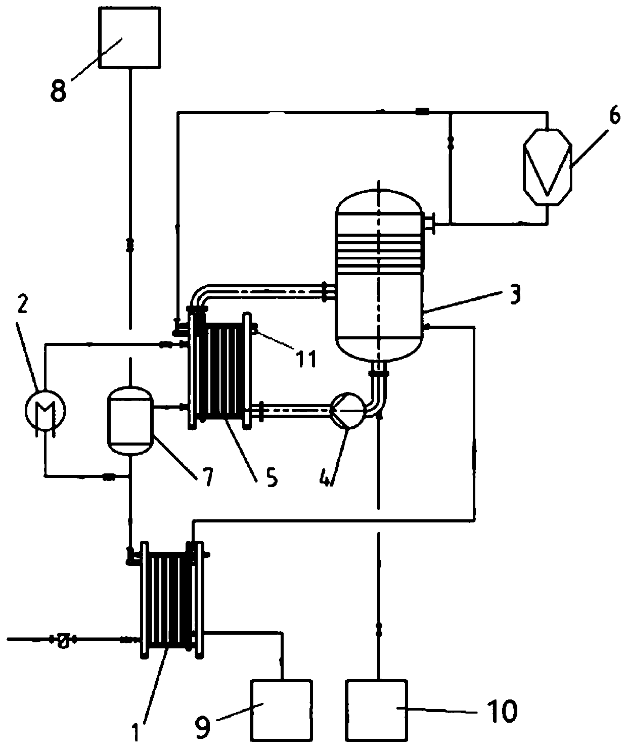
[0038] Nuclear power plant radioactive waste liquid MVR evaporation system, such as figure 1 As shown, it includes a preheater 1, an electric heating device 2, an evaporation tower 3, a circulation pump 4, a heater 5, a steam compressor 6 and a distillation tank 7.

[0039] The preheater 1 is a heat exchanger, and the inside of the preheater 1 is divided into two independent spaces, and the two independent spaces respectively flow through two streams of fluids with different temperatures for heat exchange, correspondingly, each The independent space has at least one entrance and one exit. One side...


PUM


Abstract

The invention discloses an MVR evaporation system for radioactive waste liquid in a nuclear power station. The MVR evaporation system comprises a preheater, an evaporation tower, a circulating pump, aheater, a steam compressor, an electric heating device and a distillation tank, wherein the heater is located out of the evaporation tower; an inlet and an outlet in one side of the heater are communicated with the evaporation tower; the evaporation tower is communicated with the steam compressor; an outlet of the steam compressor is communicated with an inlet in the other side of the heater; anoutlet in the other side of the heater is communicated with the distillation tank; and two ends of the electric heating device are respectively connected with the other-side inlets of the distillationtank and the heater. An operation method based on the evaporation system comprises the following steps: step a, starting a liquid inlet pump, and adding to-be-treated feed liquid to the evaporation tower until a specified liquid level is reached; step b, starting the circulating pump, the electric heating device and a distillation pump; step c, starting the steam compressor and a liquid sprayingpump; and step d, turning off the electric heating device and the distillation pump. According to the invention, radioactive waste liquid of the nuclear power station is efficiently treated, radioactive pollution is reduced, and latent heat of secondary steam generated by the waste liquid is recycled.

Description

technical field [0001] The invention belongs to the technical field of nuclear power plant radioactive waste liquid treatment and disposal, in particular to a nuclear power plant radioactive waste liquid MVR evaporation system and an operating method thereof. Background technique [0002] During the operation of nuclear power plants, various radioactive waste liquids will be produced. Many current radioactive waste liquid treatment systems in nuclear power plants use natural circulation evaporators or externally heated forced circulation evaporators. However, both the natural circulation evaporator and the forced circulation evaporator adopt the ordinary normal pressure evaporation process, which needs to continuously input new steam to heat the feed liquid, which consumes a lot of energy. For the large amount of secondary steam generated in the evaporator, the cooling water is directly used for condensation, and the heat energy cannot be recovered and the cooling water is c...

Claims


Application Information

Patent Timeline
Patent Type & Authority Applications(China)
IPC IPC(8): G21F9/08B01D1/28B01D1/30B01D1/00
CPCB01D1/0017B01D1/0094B01D1/28B01D1/30G21F9/08
Inventor 徐俊雄易梦华张志远李小齐
Owner 湖南汉华京电清洁能源科技有限公司
Learn More