GPS-based water depth synchronization method and equipment

A technology for synchronizing equipment and GPS signals, applied in the field of detection, can solve problems such as error, time error, GPS and water depth asynchrony, and achieve the effect of eliminating error factors

Active Publication Date: 2020-01-03
WUXI HAIYING CAL TEC MARINE TECH
View PDF13 Cites 0 Cited by
  • Summary
  • Abstract
  • Description
  • Claims
  • Application Information

AI Technical Summary

Problems solved by technology

[0005] A. The rate at which the GPS signal is transmitted to the computer is different from the measurement rate of the water depth measurement system, which leads to the possibility of multiple sounding points between two GPS positions, and the computer is likely to cause this error when selecting the sounding point;
[0006] B. In the past, the usual equipment connection method is that the GPS signal is transmitted to the computer serial port, and the water depth signal is communicated with the navigation software through the virtual serial port. There is a time error between the physical connection and the virtual connection, resulting in the difference between the GPS and the water depth. the result of the synchronization;
[0007] C. When the ship is moving, because the sounding principle of the depth sounder is to receive the echo signal of the signal sent last time to judge the bottom of the water, the actual sounding value should be the water depth of the previous frequency transmission position, and the GPS record is The current position information, so there is a time error of single-frequency signal transmission. This error can be basically ignored when the bottom is stable, but when the ship is traveling on a steep slope, this error is more obvious.

Method used


Image

  • GPS-based water depth synchronization method and equipment
  • GPS-based water depth synchronization method and equipment
  • GPS-based water depth synchronization method and equipment

Examples


Embodiment Construction

[0026] The preferred embodiments of the present invention will be described below in conjunction with the accompanying drawings. It should be understood that the preferred embodiments described here are only used to illustrate and explain the present invention, and are not intended to limit the present invention.

[0027] In order to achieve the purpose of the present invention, a GPS-based water depth synchronization method is provided in one of the embodiments of the present invention, comprising the following steps:

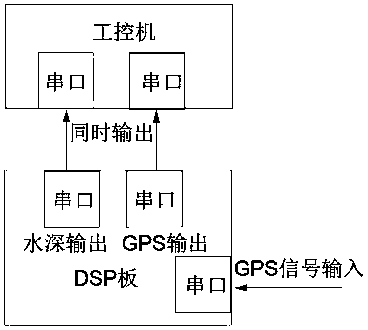
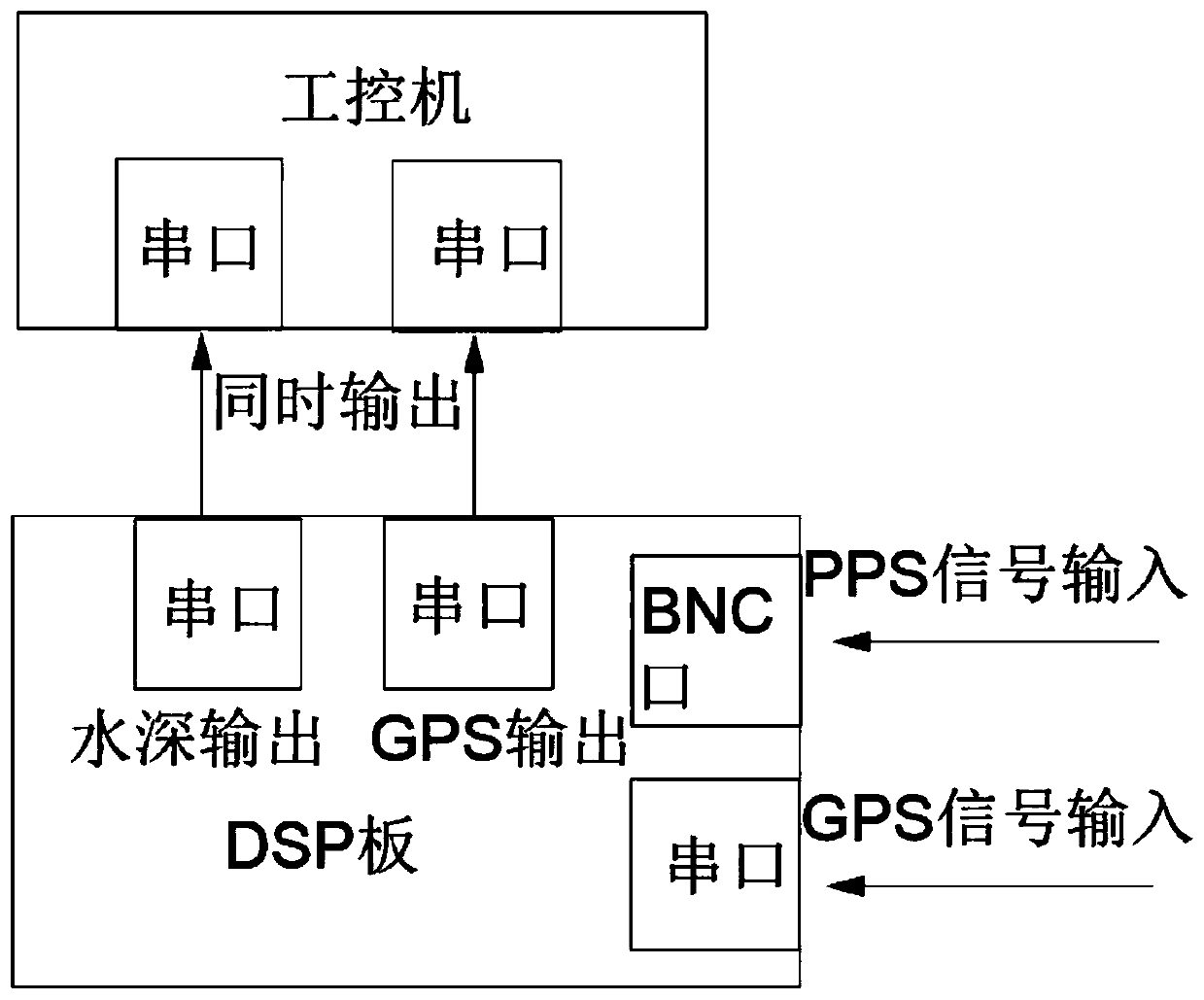
[0028] S1, GPS continuously transmits GPS signals to the DSP board;

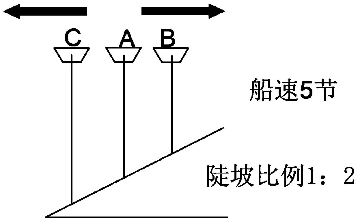
[0029] S2. According to the transmission frequency of the GPS signal, the time interval from the sounder transmitting signal to receiving the water depth signal is used as an estimated value, and the estimated value is increased before the arrival of the GPS signal to adjust the emission signal of the sounder, so that the DSP board receives simultaneously Water depth signal and GPS signal, a...


PUM


Abstract

The invention discloses a GPS-based water depth synchronization method. The method comprises the following steps of step S1, continuously transmitting a GPS signal to a DSP board by a GPS; and step S2, according to the transmission frequency of the GPS signal, taking a time interval from transmitting the signal by a depth finder to receiving a water depth signal as an estimated value to increase the estimated value before the GPS signal arrives and adjust the transmitted signal of the depth finder, so that the DSP board simultaneously receives the water depth signal and the GPS signal and synchronously sends the water depth signal and the GPS signal to an industrial personal computer. According to the GPS-based water depth synchronization method provided by the invention, the GPS and a water depth measurement technology are combined synchronously, some previous error factors are eliminated, and an increasing role in the future surveying and mapping industry is achieved; and the GPS technology is used for water depth measurement, so that the water depth measurement engineering becomes simple, fast and efficient. Therefore, the GPS and the water depth synchronization technology provide a high-precision, high-quality and high-benefit application prospect for fairway water depth measurement.

Description

technical field [0001] The invention belongs to the technical field of detection, and in particular relates to a GPS-based water depth synchronization method and equipment. Background technique [0002] Water depth signals have been widely used in various sonar devices for underwater target detection. Echo sounders are currently the most common detection equipment for distance measurement using underwater acoustic signals. Its working principle is to transmit sound waves of a certain frequency through the transducer. When sound waves propagate in water, they will generate reflection signals when encountering media with different densities (such as the bottom of the water or other objects). The propagation speed in the regional water is used to obtain the straight-line distance from the transducer to the reflection target, that is, the measured water depth. [0003] The non-tide sounding method uses the center of the GPS receiving antenna to obtain the relationship between ...

Claims


Application Information

Patent Timeline
Patent Type & Authority Applications(China)
IPC IPC(8): G01C13/00G01S19/14
CPCG01C13/008G01S19/14Y02A90/30
Inventor 吴奕斌
Owner WUXI HAIYING CAL TEC MARINE TECH
Why Eureka
Try Eureka