
Automatic assembling device of power sockets

A technology of automatic assembly and equipment, applied in assembly machines, metal processing equipment, metal processing and other directions, can solve problems such as insufficient stability, low efficiency, difficulty in maintenance and debugging, etc.

Pending Publication Date: 2020-01-03
SUZHOU E CONN TECH
View PDF0 Cites 6 Cited by
  • Summary
  • Abstract
  • Description
  • Claims
  • Application Information

AI Technical Summary

Problems solved by technology

[0002] Power socket DC JACK products are now used more and more widely, and the amount of use is increasing, and the required production capacity and quality are also getting higher and higher. In this case, the company is vigorously developing automation equipment to meet the demand and reduce labor costs. The original low-efficiency manual and jig assembly production was upgraded to a generation of automatic machine assembly, which improved the original production capacity, but the efficiency, stability and control of the equipment have fallen behind with the development of the company. The previous generation manually placed the riveting carrier, installed it on a manual punching machine, and manually adjusted it for riveting. The needle insertion mechanism of the previous generation of automatic equipment had stricter requirements on materials, lacked stability, and was difficult to maintain and debug. The company further upgrades the equipment used, researches and upgrades the stability and control of the equipment while increasing production capacity

Method used


Image

  • Automatic assembling device of power sockets
  • Automatic assembling device of power sockets
  • Automatic assembling device of power sockets

Examples


Embodiment Construction

[0042] The preferred embodiments of the present invention will be described in detail below in conjunction with the accompanying drawings, so that the advantages and features of the invention can be more easily understood by those skilled in the art, so as to define the protection scope of the present invention more clearly.

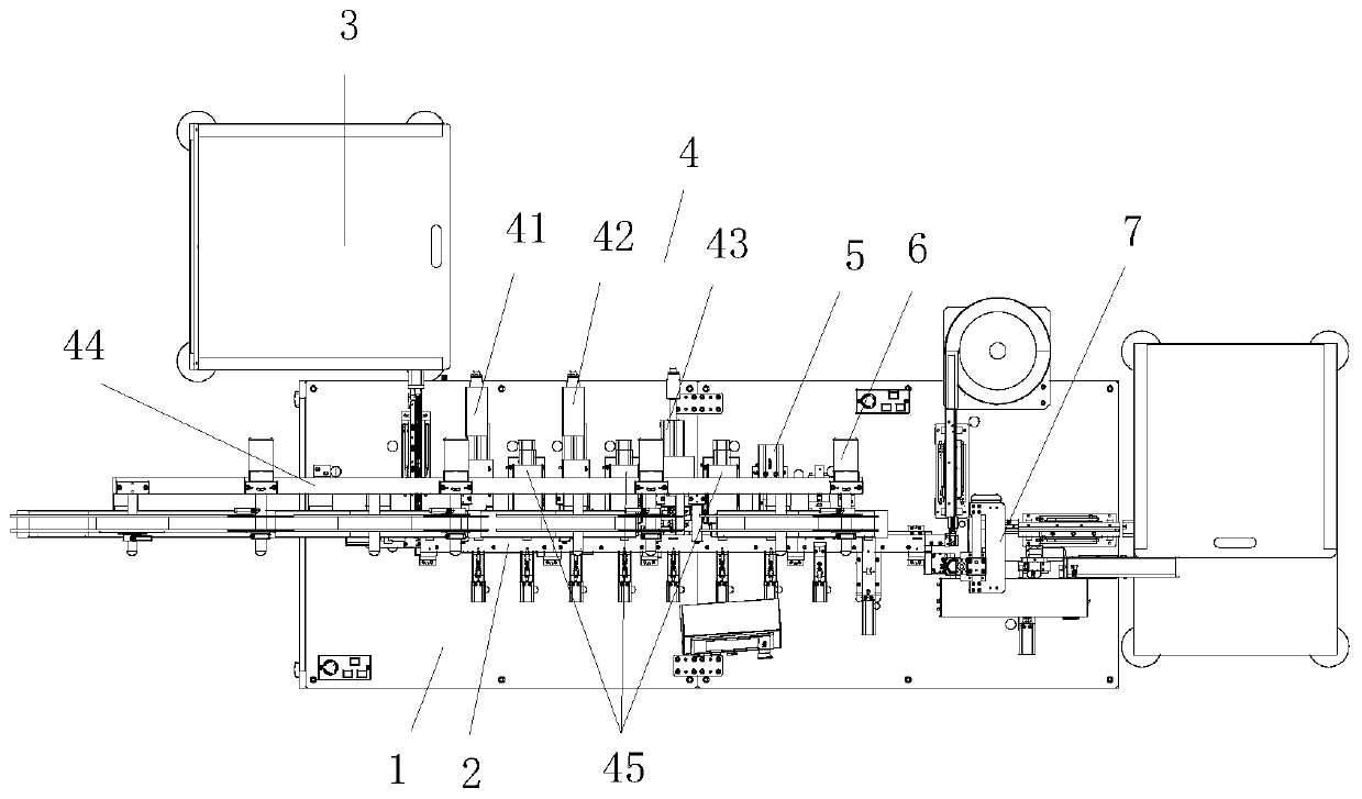
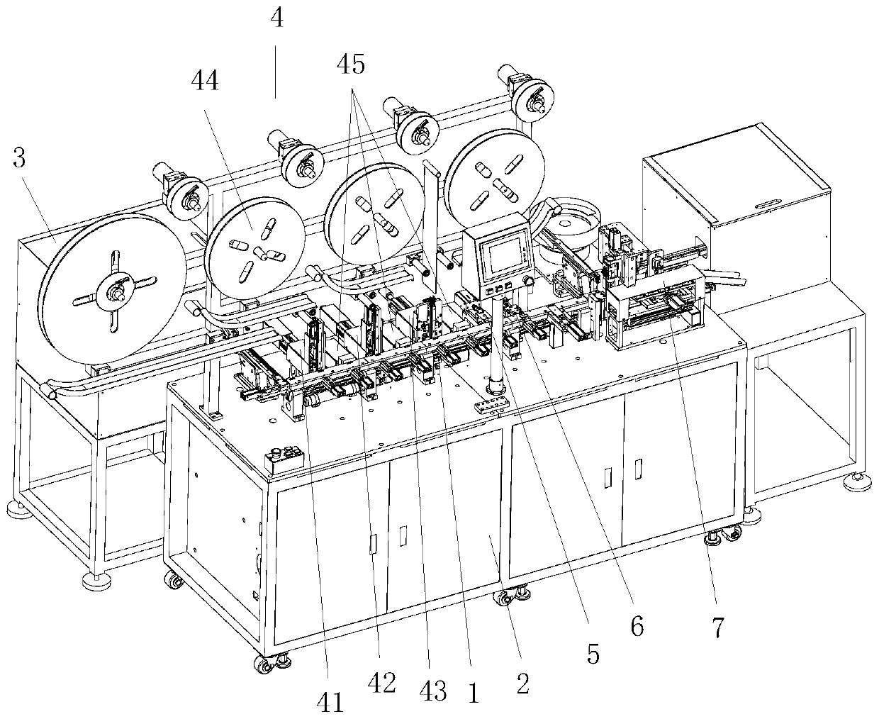
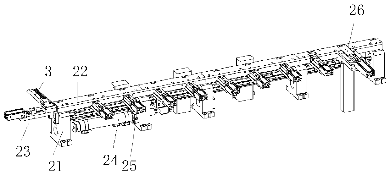
[0043] see Figure 1 to Figure 24 , the embodiment of the present invention includes:

[0044] An automatic assembly device for a power socket, the automatic assembly device for a power socket includes a positioning and transplanting linear processing flow channel 2 arranged on a frame 1, and a rubber core supply that is sequentially connected to the positioning and transplanting linear processing flow channel 2 Device 3, plug-in terminal mechanism 4, riveting mechanism 5, electric measuring mechanism 6 and bidirectional assembly mechanism 7, and a displacement recovery mechanism 8 is arranged in connection with the bidirectional assembly mechanism 7, an...


PUM


Abstract

The invention discloses an automatic assembling device of power sockets. The automatic assembling device of the power socket comprises a positioning and transplanting linear machining passageway, a rubber core supply device, a terminal inserting mechanism, a riveting mechanism, an electric measuring mechanism and a bidirectional assembling mechanism, wherein the positioning and transplanting linear machining passageway is installed on a machine frame, and the rubber core supply device, the terminal inserting mechanism, the riveting mechanism, the electric measuring mechanism and the bidirectional assembling mechanism are sequentially in butt joint with the positioning and transplanting linear machining passageway. A displacement recovery mechanism is in butt joint with the bidirectional assembling mechanism. The rubber core supply device conveys rubber cores to the positioning and transplanting linear machining passageway. The terminal inserting mechanism sequentially inserts terminalsto the rubber cores. The riveting mechanism rivets assembled products. The electric measuring mechanism comprehensively tests and judges all required functional parameters of the products. The bidirectional assembling mechanism assemblies rear plugs and iron boxes on the assembled products. In this way, the automatic assembling device is compact in structure and stable in operation, the productsneeding to be transplanted can be effectively positioned uniformly, all pin inserting mechanisms correspondingly complete work without interfering with one another in sequence, maintenance is convenient, and materials at all positions can be conveniently changed.

Description

technical field [0001] The invention relates to the technical field of industrial machinery, in particular to automatic assembly equipment for power sockets. Background technique [0002] Power socket DC JACK products are now used more and more widely, and the amount of use is increasing, and the required production capacity and quality are also getting higher and higher. In this case, the company is vigorously developing automation equipment to meet the demand and reduce labor costs. The original low-efficiency manual and jig assembly production was upgraded to a generation of automatic machine assembly, which improved the original production capacity, but the efficiency, stability and control of the equipment have fallen behind with the development of the company. The previous generation manually placed the riveting carrier, installed it on a manual punching machine, and manually adjusted it for riveting. The needle insertion mechanism of the previous generation of automat...

Claims


Application Information

Patent Timeline
IPC IPC(8): B23P21/00
CPCB23P19/001B23P19/007B23P21/004
Inventor 王发帅
Owner SUZHOU E CONN TECH
Learn More