Synchronous reluctance motor

A synchronous reluctance motor, the same technology, applied in synchronous machines, magnetic circuits, electromechanical devices, etc., can solve the problem of difficulty in designing torque ripple suppression means, achieve torque ripple suppression, reduce rotational noise, and improve motor performance. performance effect

Pending Publication Date: 2019-12-31
GREE ELECTRIC APPLIANCES INC
View PDF0 Cites 6 Cited by
  • Summary
  • Abstract
  • Description
  • Claims
  • Application Information

AI Technical Summary

Problems solved by technology

However, since the synchronous reluctance motor does not have any permanent magnets, and the rotor structure has a multi-layer magnetic flux barrier structure, the suppression method and design of torque ripple are relatively difficult.

Method used


Image

  • Synchronous reluctance motor
  • Synchronous reluctance motor
  • Synchronous reluctance motor

Examples


Embodiment Construction

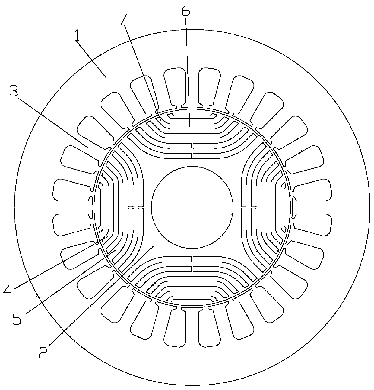
[0026] see in conjunction Figure 1 to Figure 6 As shown, according to the embodiment of the present application, the synchronous reluctance motor includes a stator core 1 and a rotor core 2, the stator core 1 includes stator teeth 3, and the rotor core 2 includes a plurality of magnetic barrier groups arranged in the circumferential direction , each magnetic barrier group includes a plurality of magnetic flux barriers 4 arranged at intervals in the radial direction, and a magnetic conduction channel 5 is formed between adjacent magnetic flux barriers 4 under the same pole, wherein the number of stator teeth N s , The number of magnetic flux barrier layers under each pole B s and the number of rotor poles 2p have the following relationship: N s / 2p=B s +1.

[0027] The number of stator teeth, the number of layers of magnetic flux barriers and the number of rotor poles are related to each other. This relationship affects the performance of the motor. This application uses th...


PUM


Abstract

The invention provides a synchronous reluctance motor. The synchronous reluctance motor comprises a stator core (1) and a rotor core (2). The stator core (1) comprises stator teeth (3). The rotor core(2) comprises a plurality of magnetic barrier groups arranged along the circumferential direction, Each magnetic barrier group comprises a plurality of magnetic flux barriers (4) arranged at radial intervals, and a magnetic conductive channel (5) is formed between the adjacent magnetic flux barriers (4) under the same pole, wherein the number of the stator teeth Ns, the number of the magnetic flux barrier layers Bs under each pole and the number of rotor poles 2p have the following relationship: Ns / 2p=Bs+1. According to the synchronous reluctance motor, the torque ripple can be effectively reduced and the motor performance can be improved.

Description

technical field [0001] The present application relates to the technical field of motors, in particular to a synchronous reluctance motor. Background technique [0002] Industrial motors are widely used in fans, water pumps, general machinery and other fields. The industry consumes more than 800 billion kWh of electricity and has great potential for energy saving. At present, IE2 asynchronous motors are still the main ones, which have low efficiency, large size, and complex processes; permanent magnet synchronous motors (IPM) can be used in some high-energy-efficiency applications to achieve IE4 or above energy efficiency, but high-performance permanent magnets usually contain rare earth components. It is difficult to save energy and reduce costs. [0003] With the continuous progress of electromagnetic and control technology, the synchronous reluctance motor without permanent magnet and simple process has become the new darling of the research on de-permanent magnetization ...

Claims


Application Information

Patent Timeline
Patent Type & Authority Applications(China)
IPC IPC(8): H02K1/22
CPCH02K1/22H02K2213/03H02K1/246H02K19/103H02K29/03H02K1/2766
Inventor 陈彬胡余生童童卢素华廖克亮李扬王勇
Owner GREE ELECTRIC APPLIANCES INC
Why Eureka
Try Eureka