
A monitoring method and device for an induction motor based on magnetic flux leakage and vibration signals

A vibration signal and monitoring device technology, which is applied in the direction of motor generator testing, measuring devices, and measuring electricity, can solve problems such as high cost and difficult deployment, and achieve the effects of reducing difficulty, optimizing configuration, and reducing losses

Active Publication Date: 2021-01-19
XI AN JIAOTONG UNIV
View PDF6 Cites 2 Cited by
  • Summary
  • Abstract
  • Description
  • Claims
  • Application Information

AI Technical Summary

Problems solved by technology

[0005] In order to solve the above problems, the present invention provides an induction motor monitoring method and device based on magnetic flux leakage and vibration signals, which solves the problems of high cost and difficult deployment in the existing monitoring technology, and provides suitable for small and medium-sized induction motors. Condition Monitoring Solution

Method used


Image

  • A monitoring method and device for an induction motor based on magnetic flux leakage and vibration signals
  • A monitoring method and device for an induction motor based on magnetic flux leakage and vibration signals
  • A monitoring method and device for an induction motor based on magnetic flux leakage and vibration signals

Examples


Embodiment Construction

[0035] The present invention will be described in detail below in conjunction with the accompanying drawings and specific embodiments.

[0036] In describing the present invention, it should be understood that the terms "center", "longitudinal", "transverse", "upper", "lower", "front", "rear", "left", "right", " The orientations or positional relationships indicated by "vertical", "horizontal", "top", "bottom", "inner" and "outer" are based on the orientations or positional relationships shown in the drawings, and are only for the convenience of describing the present invention and Simplified descriptions, rather than indicating or implying that the device or element referred to must have a particular orientation, be constructed and operate in a particular orientation, and thus should not be construed as limiting the invention. In addition, the terms "first" and "second" are used for descriptive purposes only, and cannot be interpreted as indicating or implying relative import...


PUM


Abstract

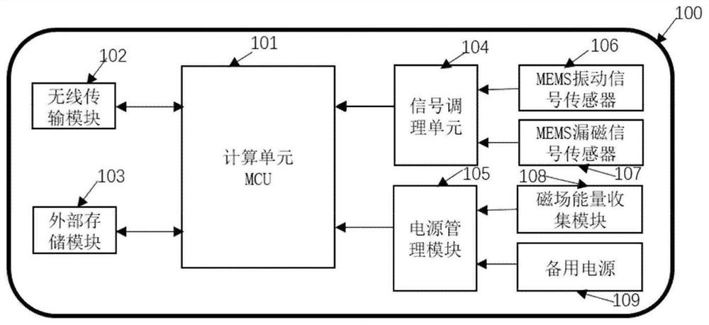
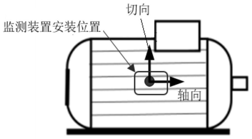
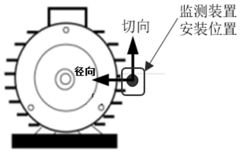
The invention discloses an induction motor monitoring method and device based on magnetic flux leakage and vibration signals. The device comprises a vibration signal sensor, a magnetic flux leakage sensor and a calculation unit. The output end of the vibration signal sensor and the output end of the magnetic flux leakage sensor are connected with the input end of the calculation unit. The magneticflux leakage sensor is used for collecting axial, radial and tangential magnetic flux leakage signals of a motor. The vibration signal sensor is used for collecting vibration signals of a case of theinduction motor. The calculation unit is used for processing the magnetic flux leakage and vibration signals to obtain a rotating speed nr, a slip ratio s, an actual torque T and a power supply frequency fs of the motor. The problems of high cost, difficult deployment and the like in the existing monitoring technology are solved, and an appropriate state monitoring scheme is provided for small and medium-sized induction motors.

Description

technical field [0001] The invention belongs to the technical field of state monitoring of motors, and in particular relates to a method and device for monitoring induction motors based on magnetic flux leakage and vibration signals. Background technique [0002] Induction motors are widely used in industry and are the main energy-consuming equipment, and motor failure will lead to high maintenance costs, huge production stop loss, and even endanger personal safety. Mastering the working state of the motor can realize the optimal allocation of energy and save costs; and mastering the health status of the motor is of great significance for timely troubleshooting and reducing economic losses. [0003] The monitoring systems commonly used in industry are based on current monitoring method and vibration monitoring method. However, current monitoring needs to collect single-phase or three-phase current of the motor, vibration monitoring method needs to measure the vibration of t...

Claims


Application Information

Patent Timeline
Patent Type & Authority Patents(China)
IPC IPC(8): G01R31/34
CPCG01R31/343
Inventor 侯成刚白德桃
Owner XI AN JIAOTONG UNIV
Learn More