Rotor core, permanent magnet motor and compressor

A rotor iron core, permanent magnet motor technology, applied in the field of compressors, can solve the problems of large proportion of reluctance torque, reduced reluctance torque, and reduced motor efficiency, so as to increase the proportion and optimize the cogging torque. , the effect of improving efficiency

Pending Publication Date: 2019-12-27
GUANGDONG MEIZHI COMPRESSOR
View PDF0 Cites 5 Cited by
  • Summary
  • Abstract
  • Description
  • Claims
  • Application Information

AI Technical Summary

Problems solved by technology

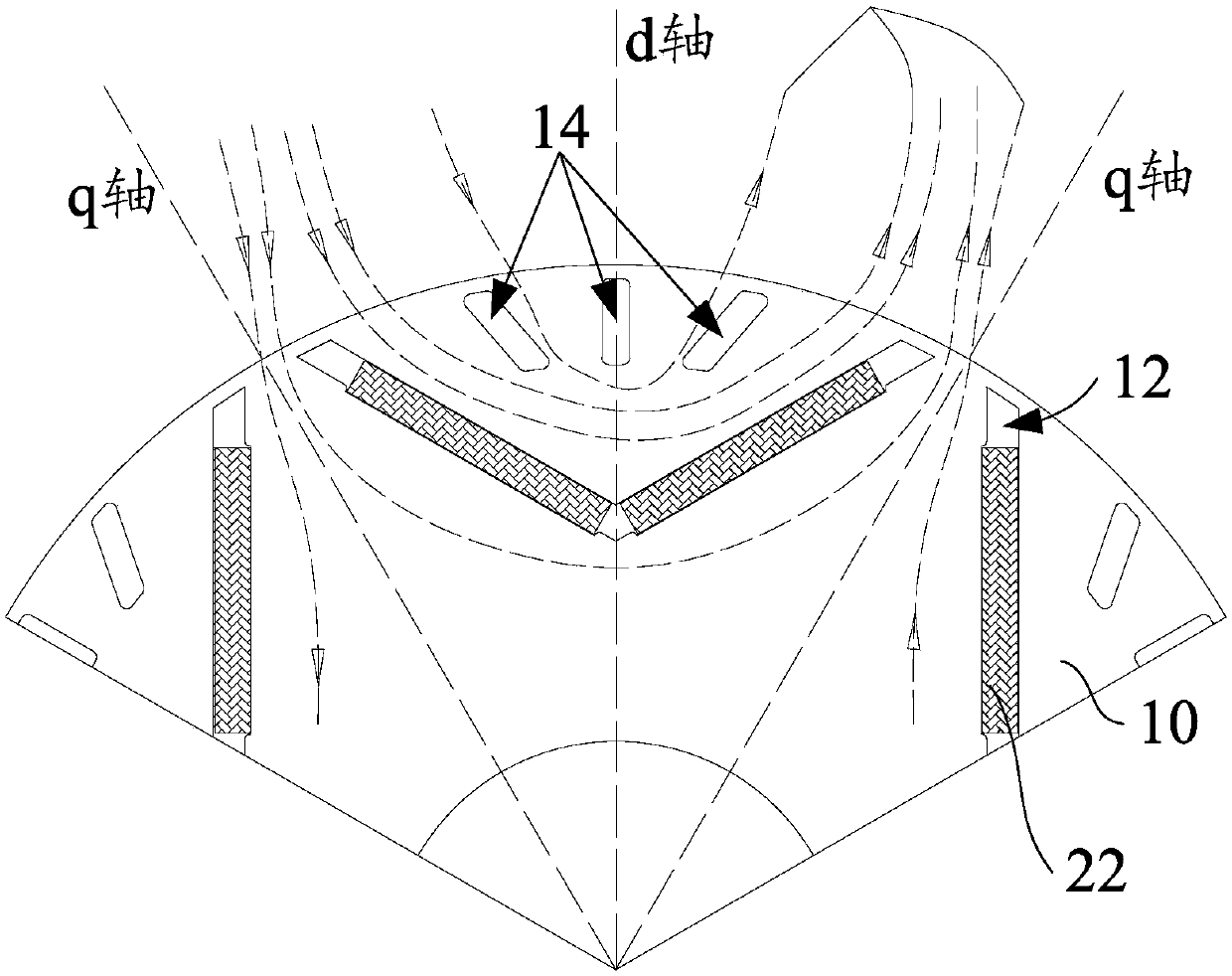
[0004] The permanent magnet motor in the prior art has the characteristics of excellent noise index by providing a slit on the outside of the permanent magnet slot of the rotor core to guide the magnetic circuit to converge to the outside of the rotor. However, this solution is only suitable for motors with small power In the field of high-power motors, since the reluctance torque accounts for a large proportion, the above scheme will bring about problems such as reducing the reluctance torque and reducing the efficiency of the motor.

Method used


Image

  • Rotor core, permanent magnet motor and compressor
  • Rotor core, permanent magnet motor and compressor
  • Rotor core, permanent magnet motor and compressor

Examples


Embodiment Construction

[0046] In order to have a clearer understanding of the above objects, features and advantages of the present invention, the present invention will be further described in detail below in conjunction with the accompanying drawings and specific embodiments. It should be noted that, in the case of no conflict, the embodiments of the present application and the features in the embodiments can be combined with each other.

[0047] In the following description, many specific details are set forth in order to fully understand the present invention. However, the present invention can also be implemented in other ways different from those described here. Therefore, the protection scope of the present invention is not limited by the specific details disclosed below. EXAMPLE LIMITATIONS.

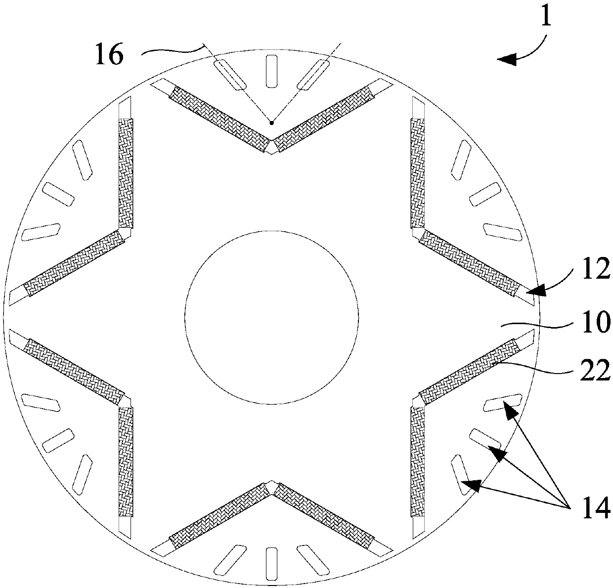
[0048] Refer below Figure 1 to Figure 10 The rotor core, permanent magnet motor and compressor according to some embodiments of the present invention are described.

[0049] like figure 1 and fig...


PUM


Abstract

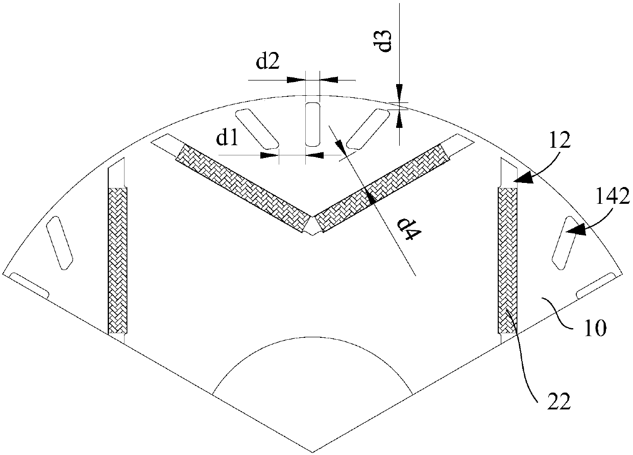
The invention provides a rotor core, a permanent magnet motor and a compressor. The rotor core comprises a plurality of permanent magnet grooves and a plurality of magnetic isolation groove groups, wherein a plurality of permanent magnet grooves penetrate through the rotor core along the axial direction of the rotor core, a plurality of magnetic isolation groove groups are respectively arranged between any one of a plurality of permanent magnet grooves and an outer contour of the rotor core, a plurality of magnetic isolation groove groups are in one-to-one correspondence with a plurality of permanent magnet grooves, and any one of a plurality of magnetic isolation groove groups comprises at least two magnetic isolation grooves, in a plane perpendicular to the central axis of the rotor core, a straight line connecting two ends of any one of the at least two magnetic isolation grooves is a magnetic isolation groove trend line, and an intersection point of the at least two magnetic isolation groove trend lines corresponding to any one of a plurality of magnetic isolation groove groups is located in the rotor core. The rotor core is advantaged in that the magnetic isolation groove groups are arranged, and the intersection point of the at least two corresponding magnetic isolation groove trend lines in any one magnetic isolation groove group is positioned in the rotor core, so the noise is reduced, and efficiency of the permanent magnet motor is improved.

Description

technical field [0001] The invention relates to the technical field of compressors, in particular to a rotor iron core, a permanent magnet motor and a compressor. Background technique [0002] Higher efficiency and lower noise of inverter compressors are important topics in the field of compressors in recent years. Permanent magnet motors, as drive motors for inverter compressors, play a vital role in the topic of higher efficiency and lower noise for compressors. [0003] The torque of the permanent magnet motor includes two parts: permanent magnet torque and reluctance torque. In the occasion of small power, such as the field of rotary compressor, the permanent magnet torque is basically the main part; however, in the occasion of high power, such as In the field of scroll compressors, the proportion of reluctance torque has increased. When designing permanent magnet motors, it is necessary to fully consider how to effectively use reluctance torque. [0004] The permanent ...

Claims


Application Information

Patent Timeline
Patent Type & Authority Applications(China)
IPC IPC(8): H02K1/27
CPCH02K1/276H02K2213/03
Inventor 乔正忠毛临书徐飞邱小华王玉龙张康程军明
Owner GUANGDONG MEIZHI COMPRESSOR
Why Eureka
Try Eureka