Transferring and packaging tray of cooling fan
A technology for cooling fans and trays, applied in the directions of packaging, transportation and packaging, rigid containers, etc., can solve the problem of the cooling fan not being fixed firmly, and achieve the effect of solving the problem of fixing the cooling fan.
- Summary
- Abstract
- Description
- Claims
- Application Information
AI Technical Summary
Problems solved by technology
Method used
Image
Examples
Embodiment 1
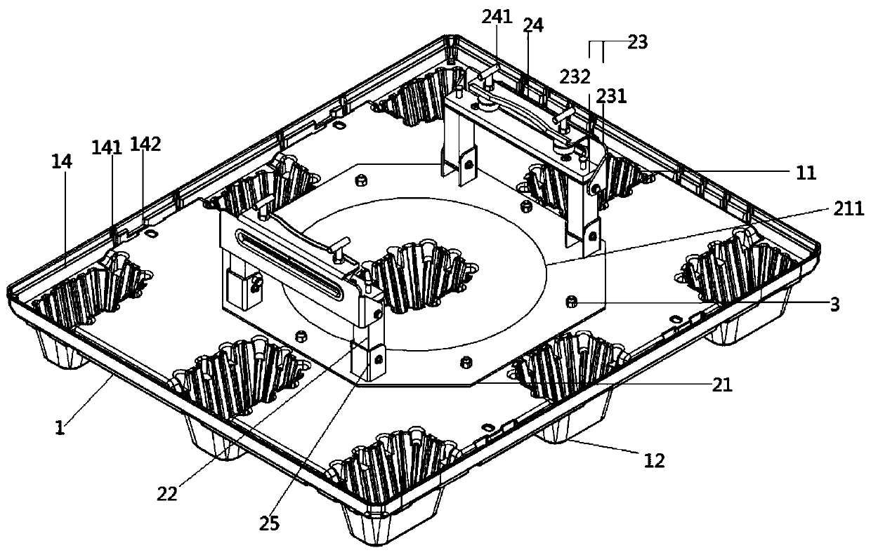
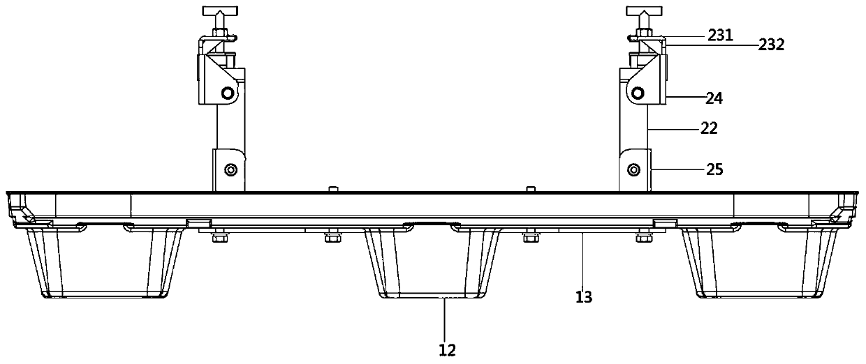
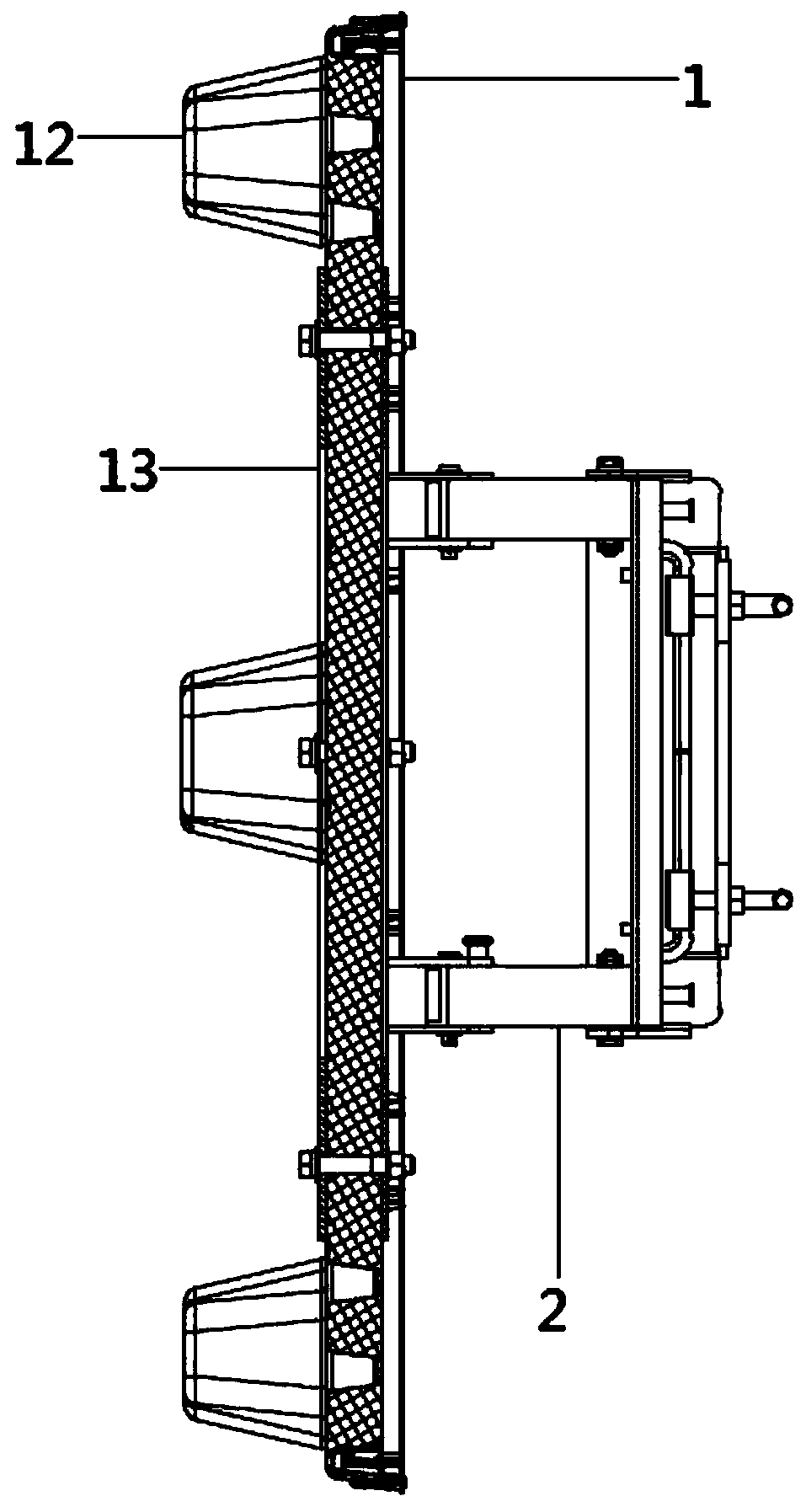
[0025] see Figure 1 to Figure 3 , the figure shows a cooling fan turnover packaging tray provided by the embodiment of the present invention, which mainly includes a tray 1 and a mounting seat assembly 2 arranged on the tray 1, the tray 1 is rectangular in plan view, and the tray 1 There are a plurality of groove structures 11 arranged in an array on the surface of the tray, and each groove structure 11 forms a corresponding raised portion 12 on the back of the tray 1, and the mounting seat assembly 2 is fixedly installed on the center of the surface of the tray 1, and the mounting seat The assembly 2 includes a base 21 and two symmetrical brackets 22, the base 21 is fixed on the tray 1 by bolts 3, the two symmetrical brackets 22 are respectively arranged at opposite ends of the base 21, and each bracket 22 is fixedly mounted with a connecting plate 23 , The connecting plate 23 is provided with a limiting plate 24 .
[0026] see Figure 1 to Figure 4 , the opposite ends of ...
Embodiment 2
[0031] see Figure 1 to Figure 4 , the figure shows a cooling fan turnover packaging tray provided by Embodiment 2 of the present invention. On the basis of the above embodiment, this embodiment further makes the following technical solutions as improvements: the connecting plate 23 includes a first The connecting plate 231 and the second connecting plate 232 , the first connecting plate 231 is vertically connected to the second connecting plate 232 , and the first connecting plate 231 is arranged along the length direction of the second connecting plate 232 .
[0032] Through the setting of the above structure, the cooling fan can be fixed conveniently, more stable support can be realized, and the shaking of the cooling fan during transportation can be reduced.
Embodiment 3
[0034] see Figure 1 to Figure 4 , the figure shows a cooling fan revolving packaging tray provided by Embodiment 3 of the present invention. On the basis of the above embodiments, this embodiment further makes the following technical solutions as improvements: a limit plate 24 The side is rotatably connected to the first connecting plate 231 , and the limiting plate 24 is provided with two limiting rods 241 , and the limiting rods 241 pass through and extend to the bottom of the first connecting plate 231 .
[0035] Through the setting of the above structure, the cooling fan can be fixed again by using the limit rod. At the same time, the limit rod can be rotated up and down, which is convenient for height adjustment, and the bottom of the limit rod is connected with a fixed round block, which can protect the cooling fan when clamping. undamaged.
PUM
 Abstract
Description
Claims
Application Information
 - R&D
- Intellectual Property
- Life Sciences
- Materials
- Tech Scout
- Unparalleled Data Quality
- Higher Quality Content
- 60% Fewer Hallucinations
Browse by: Latest US Patents, China's latest patents, Technical Efficacy Thesaurus, Application Domain, Technology Topic, Popular Technical Reports.
© 2025 PatSnap. All rights reserved.Legal|Privacy policy|Modern Slavery Act Transparency Statement|Sitemap|About US| Contact US: help@patsnap.com


