Network equipment and logic device applied to network equipment
A technology of network equipment and logic devices, which is applied in the field of network communication, can solve the problems of unable to recognize messages normally, affect CPU's shunting of messages, and achieve the effect of ensuring normal shunting
- Summary
- Abstract
- Description
- Claims
- Application Information
AI Technical Summary
Problems solved by technology
Method used
Image
Examples
Embodiment 1
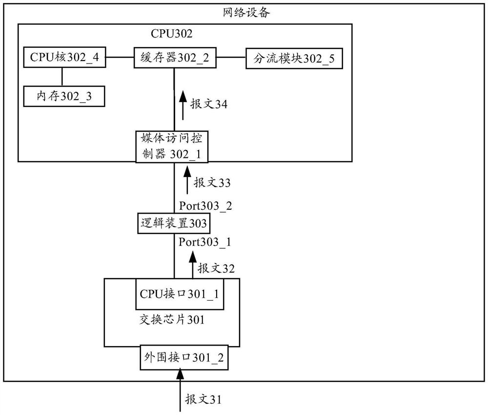
[0038] see image 3 , image 3 It is a structural diagram of a network device provided in Embodiment 1 of the present application. Such as image 3 As shown, in the structural diagram of the network device provided in Embodiment 1, the network device may include: a switch chip 301 , a CPU 302 , and a logic device 303 . The network device shown in Embodiment 1 is taken as an example including only one switch chip.
[0039] Such as image 3 As shown, the switch chip 301 may include a CPU interface 301_1 and a peripheral interface 301_2. Here, the number of peripheral interfaces 301_2 is greater than or equal to one. The peripheral interface is used for receiving messages outside the switch chip 301 and for sending messages outside the switch chip 301 .
[0040] Such as image 3 As shown, the CPU 302 includes at least: a media access controller 302_1 , a buffer 302_2 , a memory 302_3 , a CPU core 302_4 , and a distribution module 302_5 . The number of CPU cores 302_4 is g...
Embodiment 2
[0061] see Figure 5 , Figure 5 It is a structural diagram of a network device provided by Embodiment 2 of the present application. Such as Figure 5 As shown, in the structural diagram of the network device provided in Embodiment 2, the network device may include: a switch chip 501 , a CPU 502 , and a logic device 503 . The network device shown in Embodiment 2 is taken as an example including only one switch chip.
[0062] Such as Figure 5 As shown, the switch chip 501 may include a CPU interface 501_1 and a peripheral interface 501_2.
[0063] The CPU 502 includes at least: a media access controller 502_1 , a buffer 502_2 , a memory 502_3 , a CPU core 502_4 , and a distribution module 502_5 .
[0064] In Embodiment 2, the CPU interface 501_1 of the switch chip 501 is connected to the media access controller 502_1 of the CPU 502 .
[0065] In the second embodiment, the logic device 503 is connected between the media access controller 502_1 and the buffer 502_2.
[00...
Embodiment 3
[0082] see Figure 6 , Figure 6 A structural diagram of a network device provided in Embodiment 3 of the present application. Such as Figure 6 As shown, in the structural diagram of the network device provided in Embodiment 3, the network device may include: a switch chip 601 and a CPU 602 . The network device shown in Embodiment 3 is taken as an example including only one switch chip.
[0083] In Embodiment 3, the structure of the switch chip 601 is similar to that of the switch chip 301 in Embodiment 1 and the structure of the switch chip 501 in Embodiment 2, and will not be repeated here.
[0084]In Embodiment 3, the CPU 602 at least includes: a module 600 , a buffer 602_1 , a memory 602_2 , a CPU core 602_3 , and a distribution module 602_4 . Wherein, the module 600 is composed of a media access controller 600_1 and a logic device 600_2.
[0085] In the third embodiment, the media access controller 600_1 and the logic device 600_2 can be set in the module 600 accord...
PUM
 Abstract
Description
Claims
Application Information
 - R&D
- Intellectual Property
- Life Sciences
- Materials
- Tech Scout
- Unparalleled Data Quality
- Higher Quality Content
- 60% Fewer Hallucinations
Browse by: Latest US Patents, China's latest patents, Technical Efficacy Thesaurus, Application Domain, Technology Topic, Popular Technical Reports.
© 2025 PatSnap. All rights reserved.Legal|Privacy policy|Modern Slavery Act Transparency Statement|Sitemap|About US| Contact US: help@patsnap.com


