
Interrupt detection device and method

A detection device and detection method technology, applied in the direction of measuring device, measuring electricity, measuring electrical variables, etc., can solve problems such as poor versatility, unstable level, increased probability of plug error, etc., to reduce the complexity of hardware circuits and software , reduce the cost of the whole machine, and reduce the effect of labor costs

Active Publication Date: 2016-01-20
HUAQIN TECH CO LTD
View PDF6 Cites 0 Cited by
  • Summary
  • Abstract
  • Description
  • Claims
  • Application Information

AI Technical Summary

Problems solved by technology

[0005] The technical problem to be solved by the present invention is to overcome the problem in the prior art when detecting whether the inserted plug is an earphone or an incoming electric flash by adding a dedicated ADC interrupt detection circuit on the hardware and identifying it in combination with software, resulting in a large amount of manpower and hardware resources being occupied. Increase the logic complexity of the software and the cost of the whole machine, the versatility is poor, and the use of the ADC interrupt detection circuit needs to consider the anti-shake time, the level is unstable when the plug is inserted, and the error probability of plug recognition increases when the plug is inserted too slowly. , provides an interrupt detection device and method, which has the advantages of reducing the complexity of hardware circuits and software, reducing the cost of the whole machine, cross-platform application, no need to consider anti-shake time and accurate identification, etc.

Method used


Image

  • Interrupt detection device and method
  • Interrupt detection device and method
  • Interrupt detection device and method

Examples


Embodiment 1

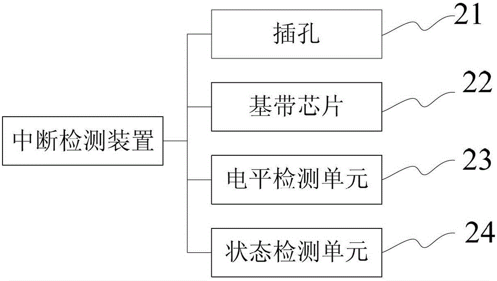
[0046] Such as image 3 As shown, the interrupt detection device of the present embodiment includes a jack 21, a baseband chip 22, a level detection unit 23 and a state detection unit 24, the jack 21 includes a DETECT pin 4, and the baseband chip 22 uses MTK (MediaTek, MediaTek Co., Ltd.) platform baseband chip as an example.

[0047] Wherein, the level detection unit 23 is used to detect whether the LAUDIO pin of a plug is connected to the DETECT pin 4, if so, the level detection unit 23 generates a trigger signal and transmits it to the baseband chip 22, the baseband The chip 22 starts the state detection unit 24 after receiving the trigger signal, if not, the level detection unit 23 continues to detect whether the LAUDIO pin of the plug is connected to the DETECT pin 4 .

[0048] The state detection unit 24 is used to detect whether the MIC pin of the plug is connected to the DETECT pin 4, if so, the state detection unit 24 generates a state value and transmits it to the b...

Embodiment 2

[0063] The interrupt detection device in this embodiment includes the same components as the interrupt detection device in Embodiment 1, wherein the circuit structure of the level detection unit in this embodiment is the same as the circuit structure of the level detection unit in Embodiment 1 The same, but the circuit structure of the state detection unit in this embodiment is different from the circuit structure of the state detection unit in Embodiment 1.

[0064] Such as Image 6 As shown, the state detection unit of this embodiment includes a power supply, a first resistor R1' of 540KΩ, a switch, a second resistor R2' of 110KΩ, a third resistor R3' of 1220KΩ, and a fourth resistor R4' It is 350KΩ, a first comparator and a second comparator. The power supply is grounded through the first resistor R1', the switch, the second resistor R2', the third resistor R3' and the fourth resistor R4' connected in sequence, and the second resistor R2' and the third resistor R3' is con...


PUM


Abstract

The invention discloses an interrupt detecting device and an interrupt detecting method. The interrupt detecting device comprises a plug hole, a baseband chip, an electrical level detecting unit and a state detecting unit. The plug hole comprises a DETECT pin. The electrical level detecting unit is used to detect whether a LAUDIO pin of the plug pin is connected with the DETECT pin. If the LAUDIO pin is connected with the DETECT pin, a trigger signal is generated by the electrical level detecting unit and transmitted to the baseband chip. When receiving the trigger signal, the baseband chip starts the state detecting unit. The state detecting unit is used to detect whether a MIC pin is connected with the DETECT pin. If the MIC pin is connected with the DETECT pin, a state value is generated by the state detecting unit and transmitted to the baseband chip. The baseband chip receives the state value and judges whether a plug is connected with a cellphone flash or an earphone based on the state value. The interrupt detecting device and the interrupt detecting method have the advantages that stabilization time does need considering and identification of the plug by the interrupt detecting device is not affected by excessively rapid or slow plugging of the plug and the like.

Description

technical field [0001] The invention relates to a detection device and method, in particular to an interruption detection device and method. Background technique [0002] At present, the incoming call flash has the function of indicating some statuses of mobile devices such as mobile phones, such as missed calls, new short messages, and no battery power. And most of the mobile phones that have appeared use the earphone and the incoming call flash to share the same interface. This method needs to strictly distinguish the inserted earphone from the incoming call flash. Now the commonly used detection method is to identify earphones and incoming call flashes by adding a special detection circuit to the hardware of the mobile phone and combining software. This detection method not only takes up a lot of manpower for software development, but also increases the logic complexity of the software. A dedicated ADC interrupt (ADC interrupt is a designer-defined interrupt) detection c...

Claims


Application Information

Patent Timeline
Patent Type & Authority Patents(China)
IPC IPC(8): G01R31/04
Inventor 易伟徐敏
Owner HUAQIN TECH CO LTD
Learn More