Engine revolution speed fixing device

A technology of engine speed and fixing device, applied in the direction of engine control, machine/engine, mechanical equipment, etc., can solve problems such as high driving intensity, and achieve the effect of reducing driving intensity

Pending Publication Date: 2019-12-24
TIANJIN PORT HUISHENG TERMINAL
View PDF0 Cites 0 Cited by
  • Summary
  • Abstract
  • Description
  • Claims
  • Application Information

AI Technical Summary

Problems solved by technology

[0002] At present, tire crane drivers generally need to keep the engine running at high speed for a long time during operation, and the outrigger operating lever of the crane is located outside the driver's cab. When controlling the operating lever to adjust the outrigger expansion and contraction, the engine speed must be maintained to provide the power for outrigger expansion and contraction, resulting in Operating drivers need to bear greater driving intensity during the operation

Method used


Image

  • Engine revolution speed fixing device
  • Engine revolution speed fixing device

Examples


Embodiment Construction

[0015] The present invention will be further described below in conjunction with the accompanying drawings and specific embodiments, but the following embodiments in no way limit the present invention.

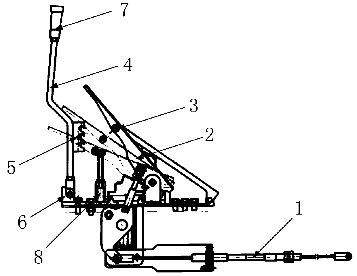
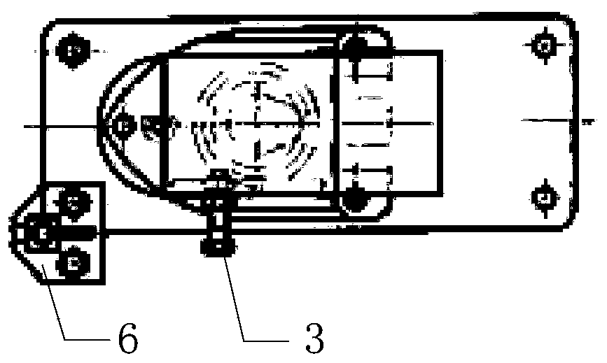
[0016] Such as figure 1 As shown, the engine speed fixing device is directly installed on the existing accelerator pedal (hereinafter referred to as the pedal) and the pedal mounting plate of the fixed pedal in the vehicle cab, which includes an angle limiting block 3, a joystick 4, an angle limiting groove 5 and a control lever. rod base 6; wherein,

[0017] The joystick base 6 is fixed on any corner of the pedal mounting plate on the back side of the pedal 2 by bolts, and its top surface is provided with a through groove with a size compatible with the size of the joystick 4 along the long side of the pedal mounting plate. The bottom end of the joystick 4 is set in the through groove and the joystick 4 is movably connected to the pedal mounting plate through the pin shaft r...


PUM


Abstract

The invention discloses an engine revolution speed fixing device. The engine revolution speed fixing device comprises an angle stopping block, a control lever, an angle limiting groove and a control lever base. The control lever base is fixed to any vertical angle position of a pedal mounting plate located on the back side of a pedal. A through groove allowing the control lever to be mounted is formed in the top face of the control lever base, and the through groove and the control lever base are movably connected through a pin shaft. The angle limiting groove is fixed to the side wall of thecontrol lever, and multiple clamping grooves tilting upwards from the side wall surface are formed in the angle limiting groove at intervals from top to bottom. The angle stopping block is composed ofa cylindrical body and a limiting piece fixed to the outer side end of the cylindrical body so that the pedal can be arranged in the different clamping grooves through the angle stopping block, and the pedal can be fixed at different trampling angles. By adoption of the engine revolution speed fixing device, vehicle engines can be kept to operate at a high revolution speed as required in the operational process of a driver, and the driving intensity of the driver is relieved.

Description

technical field [0001] The invention relates to the technical field of tire crane auxiliary devices, in particular to an engine speed fixing device. Background technique [0002] At present, tire crane drivers generally need to keep the engine running at high speed for a long time during operation, and the outrigger operating lever of the crane is located outside the driver's cab. When controlling the operating lever to adjust the outrigger expansion and contraction, the engine speed must be maintained to provide the power for outrigger expansion and contraction, resulting in Operating drivers need to bear greater driving intensity during the operation process. Therefore, it is necessary to design a speed fixing device that can be installed in the cab of the tire crane, so that the operator can fix the speed at a certain speed value according to the needs, so as to realize the purpose of convenient operation and effectively reduce the driving intensity. Contents of the inv...

Claims


Application Information

Patent Timeline
Patent Type & Authority Applications(China)
IPC IPC(8): F02D11/02F02D29/02
CPCF02D11/02F02D29/02
Inventor 李罕勇李宗生鲍永国李志刚左保驹徐莉莎薛礼刘聪周学龙邵飞孙新王志刚张军高国胜马金玲
Owner TIANJIN PORT HUISHENG TERMINAL
Why Eureka
Try Eureka