
Electronic plate cutting machine assembly

A cutting machine and component technology, applied in the direction of clamping angle iron, clamping device, etc., can solve the problems of inability to adjust and fix the installation position, and achieve the effect of improving work efficiency, ensuring position accuracy and low manufacturing cost

Inactive Publication Date: 2019-12-24
合肥恒业家具有限公司
View PDF1 Cites 2 Cited by
  • Summary
  • Abstract
  • Description
  • Claims
  • Application Information

AI Technical Summary

Problems solved by technology

[0004] In the above scheme, the piston cylinder is used to push the pressure plate to compress the wooden boards. The installation position is fixed and cannot be adjusted, so that it can only be used for compacting wooden boards in a small area, so it needs to be improved.

Method used


Image

  • Electronic plate cutting machine assembly
  • Electronic plate cutting machine assembly

Examples


Embodiment Construction

[0018] In order to make the technical means, creative features, goals and effects achieved by the present invention easy to understand, the technical solutions in the embodiments of the present invention will be clearly and completely described below in conjunction with the accompanying drawings in the embodiments of the present invention. Obviously, the The described embodiments are only some, not all, embodiments of the present invention. Based on the embodiments of the present invention, all other embodiments obtained by persons of ordinary skill in the art without creative efforts fall within the protection scope of the present invention.

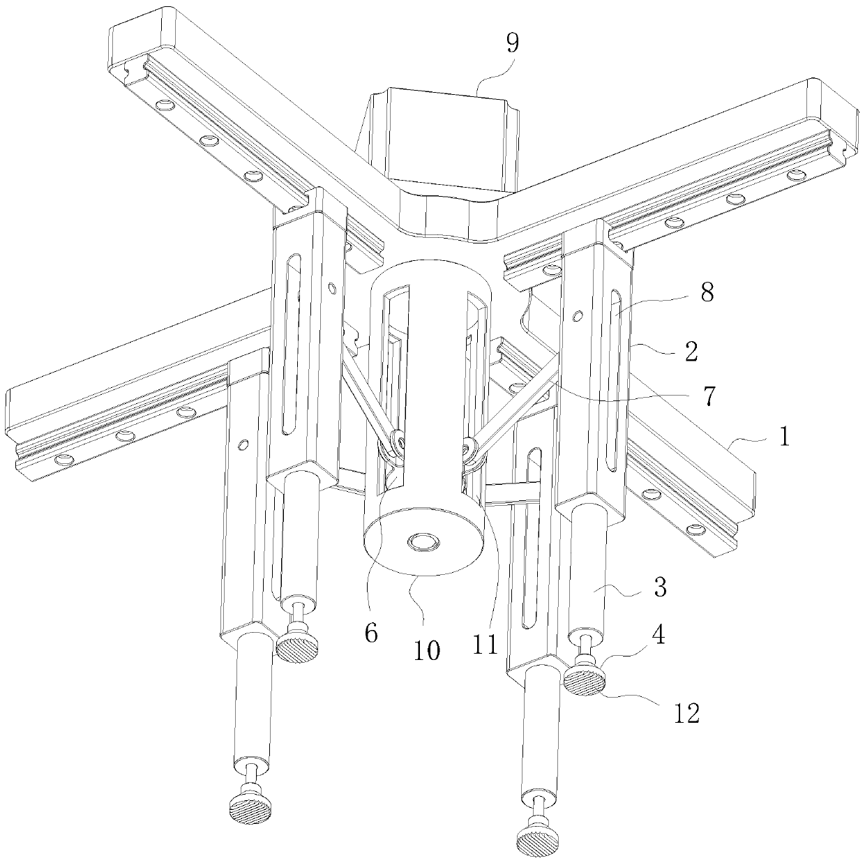
[0019] Such as Figure 1-2 The electronic cutting machine assembly shown includes a mounting plate 1 installed horizontally on an external electronic cutting machine through welding or screw connection, and the bottom surface of the mounting plate 1 is symmetrically provided with four sliding rails and sliding blocks. The sliding seat ...


PUM


Abstract

The invention relates to the technical field of plate cutting machines, in particular to an electronic plate cutting machine assembly. The electronic plate cutting machine assembly comprises a mounting plate, sliding seats, air cylinders, pressing blocks and a driving device; and the driving device comprises a ball screw, a screw nut, a hinge rod and a transmission piece. The electronic plate cutting machine assembly has the beneficial effects that the driving device drives the four sliding seats to move relatively, namely, relatively close to and far away, so that the pressing positions of the four pressing blocks can be adjusted, the device is suitable for cutting a wood plate in a large area range, the compatibility of equipment is improved, the operation efficiency is improved, in addition, the structure is simple, the manufacturing cost is low, the moving synchronization precision of the four sliding seats is high, and the position precision of the four pressing blocks is guaranteed, in addition, the pressing positions of the four pressing blocks on the wood plate can ensure that the four pressing blocks are symmetrically arranged with the appearance of the wood plate, so thatthe pressing force on the wood plate is uniform, the phenomenon that the wood plate is stressed unevenly to cause swings when the wood plate is cut is avoided, and the influence on the cutting quality is avoided.

Description

technical field [0001] The invention relates to the technical field of cutting machines, in particular to an electronic cutting machine component. Background technique [0002] Electronic panel saw (electronic panel cutting machine), that is, the use of fully automatic touch screen control, the worker inputs the data that needs to be cut on the touch screen, starts the machine, the machine runs automatically, and accurately cuts the plate that needs to be processed. Man-machine integration Operated CNC cutting machine. [0003] The prior art Chinese Patent No. CN201620968117.3 discloses an electronic panel cutting machine. The key points of its technical solution are to include a workbench connected with a pressing device located above the workbench and sliding along the Z-axis of the workbench, The spindle trolley slides along the Y-axis of the workbench and the feeding device slides along the X-axis of the workbench; the spindle trolley is rotatably connected with a saw b...

Claims


Application Information

Patent Timeline
Patent Type & Authority Applications(China)
IPC IPC(8): B27B29/02
CPCB27B29/02
Inventor 杨业贵
Owner 合肥恒业家具有限公司
Learn More