
Spline structure integrated with multi-stage vibration absorbing function

A secondary vibration reduction and spline technology, applied in transmission parts, belts/chains/gears, mechanical equipment, etc., can reduce vibration and spline tooth percussion, spline percussion abnormal noise, cost increase, etc. problems, to achieve the effect of improving service life, preventing resonance, and being easy to assemble

Pending Publication Date: 2019-12-20
华域动力总成部件系统(上海)有限公司
View PDF0 Cites 0 Cited by
  • Summary
  • Abstract
  • Description
  • Claims
  • Application Information

AI Technical Summary

Problems solved by technology

[0002] The spline is a structure that realizes torque transmission and self-aligning functions. Through the definition of the accuracy level of the spline, the accuracy of the spline is improved to reduce the side clearance of the spline tooth, so as to reduce the vibration and knocking of the spline teeth. Improving the processing accuracy of the spline will lead to a linear increase in cost
[0003] At present, splines are widely used in various powertrain systems of automobiles. For example, in structures such as manual transmissions, automatic transmissions, and continuously variable transmissions, the traditional spline structure will inevitably have spline teeth due to assembly requirements. The side clearance leads to vibration and knocking of the spline teeth, which will directly lead to the fracture of the spline, and the abnormal sound of the knocking of the spline can be heard in the cab.

Method used


Image

  • Spline structure integrated with multi-stage vibration absorbing function
  • Spline structure integrated with multi-stage vibration absorbing function
  • Spline structure integrated with multi-stage vibration absorbing function

Examples


Embodiment Construction

[0026] Embodiments of the present invention will be described in detail below in conjunction with the accompanying drawings. The main shock absorber mentioned in this embodiment refers to a component with a shock absorbing function such as a dual-mass flywheel or a shock absorbing driven plate.

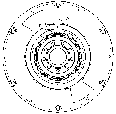
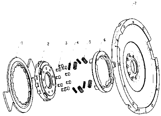
[0027] figure 1 A schematic cross-sectional view of the assembly of the present invention is shown; figure 2 A schematic diagram of the damping function of the present invention is shown; image 3 Shows the exploded view of the structure of the present invention; Figure 4 A performance graph of the invention is shown. Such as Figure 1-Figure 4 As shown, the present invention provides a spline structure with integrated multi-stage vibration damping function, including torsion transmission plate 1, main body spline 2, rivet 3, secondary spring 4, primary spring 5, vibration damping spline 6 and The flywheel disc 7 and the torsion transmission plate 1 are used as the input of the...


PUM


Abstract

The invention discloses a spline structure integrated with a multi-stage vibration absorbing function. The spline structure integrated with the multi-stage vibration absorbing function comprises a main body spline and a vibration absorbing spline; the positions, corresponding to missing teeth on the main body spline, on spline teeth arranged on the vibration absorbing spline are assembled in a filled and embedded manner to form a complete spline structure in which the spline teeth on the vibration absorbing spline and the spline teeth on the main body spline are uniformly distributed in a non-radial direction; spring components are embedded into a spring grooves in the main body spline and the vibration absorbing spline to be assembled and fixed to the position of a spring groove in a flywheel disc in a corresponding manner and then are connected with the spline teeth arranged on a torque transmission plate to transmit a torque; the torque transmission plate is connected with an inputof a main vibration absorber; and the spline structure is formed to optimize a primary vibration absorbing torque and a secondary vibration absorbing torque of the main vibration absorber. The splinestructure integrated with the multi-stage vibration absorbing function has the advantages that the problem of limited vibration absorbing ability of the main vibration absorber in a whole vehicle is solved, the torsion angle of a whole vibration absorbing system is increased, and the driving comfort of the whole vehicle is improved.

Description

technical field [0001] The invention relates to a spline structure integrating multi-stage damping functions, which is applied to various internal and external spline interfaces for transferring torque in the power assembly system of an automobile. Background technique [0002] The spline is a structure that realizes torque transmission and self-aligning functions. Through the definition of the accuracy level of the spline, the accuracy of the spline is improved to reduce the side clearance of the spline tooth, so as to reduce the vibration and knocking of the spline teeth. Improving the processing accuracy of the spline will lead to a linear increase in cost. [0003] At present, splines are widely used in various powertrain systems of automobiles. For example, in structures such as manual transmissions, automatic transmissions, and continuously variable transmissions, the traditional spline structure will inevitably have spline teeth due to assembly requirements. The side...

Claims


Application Information

Patent Timeline
Patent Type & Authority Applications(China)
IPC IPC(8): F16H57/12F16F15/30
CPCF16H57/12F16F15/30
Inventor 邱毅凡陈祥
Owner 华域动力总成部件系统(上海)有限公司
Learn More