
Discharge method for accumulated liquid at bottom of water-producing gas well

A technology for accumulating liquid and water and gas, which is applied in earth-moving drilling, wellbore/well components, and production fluids, etc. It can solve the problems of increasing gas layer back pressure, insufficient power, and low natural productivity, and achieve the effect of easily discharging liquid.

Inactive Publication Date: 2019-12-20
SOUTHWEST PETROLEUM UNIV
View PDF9 Cites 1 Cited by
  • Summary
  • Abstract
  • Description
  • Claims
  • Application Information

AI Technical Summary

Problems solved by technology

[0002] Most of the gas reservoirs in my country are low-permeability gas reservoirs, which generally have the characteristics of low porosity and low permeability. The natural energy of the reservoirs is insufficient, and the natural production capacity is low. At the same time, some low-permeability gas reservoirs are gas and water in the same layer. Or water is produced due to edge and bottom water intrusion, or residual water from fracturing. In the early stage of production, gas wells have a large output and a high flow rate, and the gas may carry water out of the wellbore. Deeper, the formation energy gradually decreases, formation water also appears, and the liquid-carrying capacity of natural gas weakens, resulting in increasing wellbore fluid accumulation. If the wellbore fluid accumulation cannot be discharged in time, the wellhead pressure will decrease, thereby increasing the impact of liquid on the gas layer. The back pressure of the natural gas will lead to a sharp drop in natural gas production, and even the phenomenon of dead wells. However, the simple single water pump is obviously insufficient in power and difficult to exhaust.

Method used


Image

  • Discharge method for accumulated liquid at bottom of water-producing gas well
  • Discharge method for accumulated liquid at bottom of water-producing gas well
  • Discharge method for accumulated liquid at bottom of water-producing gas well

Examples


Embodiment Construction

[0020] The following embodiments can be combined to enable those skilled in the art to understand the present invention more comprehensively, but the present invention is not limited to the scope of the described embodiments.

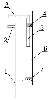
[0021] according to figure 1 A method for removing liquid accumulation at the bottom of a water-producing gas well includes the following steps: installation of gas production pipeline facilities in the well, inserting a riser pipe 6 into the gas production pipe 1 in the well, and a drain pipe 6 is installed on the top of the riser pipe 6 Pump 4, the bottom of the riser pipe 6 is equipped with a water wheel 7; to determine the height and air pressure of the liquid accumulation in the gas production pipe 1 in the well, use ultrasonic liquid level detection technology to diagnose the liquid level of the gas production pipe 1 and determine the gas production pipe 1 , The liquid accumulation height of the liquid riser pipe 6 is sensed by the pressure sensor to...


PUM


Abstract

The invention relates to a discharge method for accumulated liquid at the bottom of a water-producing gas well, and belongs to the field of gas field exploitation. Installation of a gas production pipeline facility in the well is conducted. A liquid lifting pipe is connected in a gas production pipeline in the well in an inserted manner. A liquid discharge pump is installed on the top of the liquid lifting pipe. A water wheel is installed at the bottom of the liquid lifting pipe. The accumulated liquid height and the gas pressure in the gas production pipeline in the well are judged, contrastive analysis is conducted on collected data, and whether water discharge needs to be conducted or not is judged according to the redetermined height of the liquid lifting pipe. When the liquid level height in the liquid lifting pipe is larger than a threshold value height, the liquid discharge pump is started to conduct liquid discharge. The discharge method has the beneficial effects that when liquid accumulation is generated, the accumulated liquid level of the gas production pipeline is lowered by lifting the liquid level of the liquid lifting pipe, a gas gap is formed in the liquid in the gas production pipe, the discharge gas pressure of natural gas is not influenced, and the liquid can be easily discharged through rising of the liquid level of the liquid lifting pipe.

Description

Technical field [0001] The invention belongs to the field of gas field exploitation, and specifically relates to a method for removing liquid accumulation at the bottom of a water-producing gas well. Background technique [0002] Most of the gas reservoirs in China are low-permeability gas reservoirs. Such gas reservoirs generally have the characteristics of low porosity and low permeability. The natural energy of the reservoir is insufficient and the natural productivity is low. At the same time, some low-permeability gas reservoirs are gas and water in the same layer. Or due to side and bottom water intrusion, or residual water from fracturing, resulting in water production. In the early stage of production, gas wells have large production and high flow rates, and the gas may carry water out of the wellbore. However, as the natural gas field is being exploited, with the development of Deeper, the formation energy gradually declines, and the formation water emerges. The liquid c...

Claims


Application Information

Patent Timeline
Patent Type & Authority Applications(China)
IPC IPC(8): E21B43/00E21B47/047
CPCE21B43/121
Inventor 李一宇轩陈军
Owner SOUTHWEST PETROLEUM UNIV
Learn More