Hydrostatic pressure release device for life raft

A hydrostatic pressure, life raft technology, applied in the field of underwater automatic release devices, can solve the problems of insufficient reliability, easy corrosion and dull rust, waste of resources, etc., and achieve the effects of reducing production costs, releasing safety, and strong reliability

Active Publication Date: 2021-07-13
CHINA MERCHANTS HEAVY IND JIANGSU
View PDF0 Cites 0 Cited by
  • Summary
  • Abstract
  • Description
  • Claims
  • Application Information

AI Technical Summary

Problems solved by technology

[0004] 2. The blade is in the marine climate environment for a long time, it is easy to corrode and rust, and the reliability of release is insufficient
[0005] 3. As a one-time product, the product will fail after the verification test, resulting in waste of resources

Method used


Image

  • Hydrostatic pressure release device for life raft
  • Hydrostatic pressure release device for life raft

Examples


Embodiment Construction

[0014] The specific implementation manners of the present invention will be further described below in conjunction with the drawings and examples. The following examples are only used to illustrate the technical solution of the present invention more clearly, but not to limit the protection scope of the present invention.

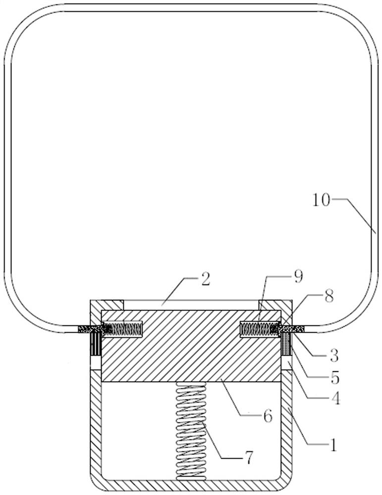
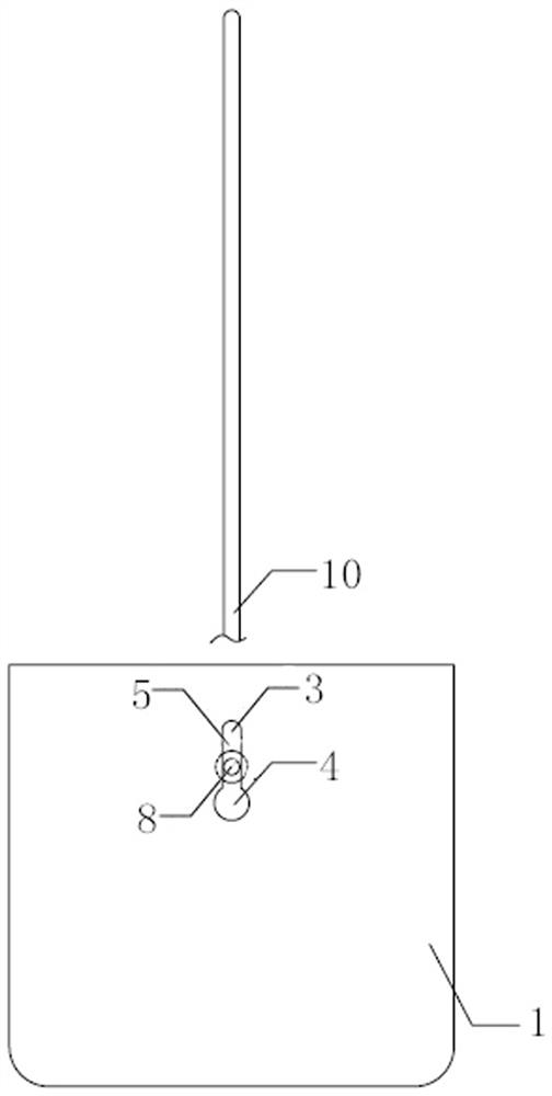
[0015] like figure 1 , figure 2 As shown, a hydrostatic pressure release device for a life raft includes a shell 1, a water inlet 2 is provided on one side of the shell 1, and an opening 3 and a breakout 4 are provided on the other two sides of the shell 1 near the water inlet 2, and the opening 3 is connected to the water inlet 2. The outlets 4 communicate with each other through the slideway 5; a diaphragm 6 is provided in the casing 1 close to the water inlet 2, and the end of the diaphragm 6 away from the water inlet 2 of the casing 1 is fixedly connected to the inner side of the casing 1 through a compression spring 7, and the membrane A release tri...


PUM


Abstract

The invention discloses a hydrostatic pressure release device for a life raft, which comprises a casing, one side of the casing is provided with a water inlet, and the other two sides are provided with an opening and a release near the water inlet, and the opening and the release are communicated through a slideway. ; There is a diaphragm near the water inlet in the shell, and the diaphragm is fixedly connected to the inner side of the shell through a compression spring. There is a release trip in the diaphragm, and a release spring is provided between the release trip and the diaphragm. The outer end of the outer shell is fixedly connected with the rope through the opening of the shell. The design principle of the invention is simple and effective, the release is safe, the reliability is strong, and it can be used repeatedly, thereby improving the resource utilization rate and reducing the production cost.

Description

technical field [0001] The invention relates to an underwater automatic release device, in particular to a hydrostatic pressure release device for a life raft. Background technique [0002] At present, the principle design of the known hydrostatic pressure release device is to release the spring blade by using the increase of water depth to generate pressure, and use the impact force of the spring to push the blade to cut the ring-shaped locking rope. The disadvantages and deficiencies of this principle design are as follows: [0003] 1. The tethering rope is a closed-loop cable, and a release device needs to be added to the closed-loop cable. The release is accomplished by cutting the tether with the blade, and the blade is released by moving the diaphragm under water pressure. The principle is slightly redundant. [0004] 2. The blade is in the marine climate environment for a long time, it is easy to corrode and rust, and the reliability of release is insufficient. [0...

Claims


Application Information

Patent Timeline
Patent Type & Authority Patents(China)
IPC IPC(8): B63B23/70
CPCB63B23/70
Inventor 石建新王军红谭晓爽王彦亮
Owner CHINA MERCHANTS HEAVY IND JIANGSU
Why Eureka
Try Eureka