
O-shaped ring die capable of being positioned

An O-ring and mold technology, applied in the field of molds, can solve the problems affecting the casting process, loosening, unstable positioning, etc., and achieve the effects of not easy to loosen, stable positioning, and not easy to bend and deform

Inactive Publication Date: 2019-12-20
苏州钧固精密模具有限公司
View PDF0 Cites 0 Cited by
  • Summary
  • Abstract
  • Description
  • Claims
  • Application Information

AI Technical Summary

Problems solved by technology

[0002] In the mold industry, various molds and tools are used for injection molding, blow molding, extrusion, die-casting or forging forming, smelting, stamping and other methods to obtain the required products. The O-ring mold is a kind of mold, but the existing O-ring mold The structure of the ring mold is relatively simple. The existing O-ring mold is only positioned by the cooperation of four guide posts and guide sleeves, and it needs to be fed with an aluminum feeder.
[0003] The existing O-ring molds are prone to looseness and unstable positioning when they are matched with the positioning, thus affecting the casting process

Method used


Image

  • O-shaped ring die capable of being positioned
  • O-shaped ring die capable of being positioned
  • O-shaped ring die capable of being positioned

Examples


Embodiment 1

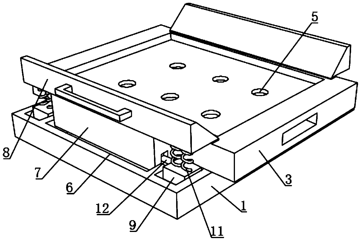
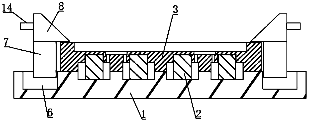
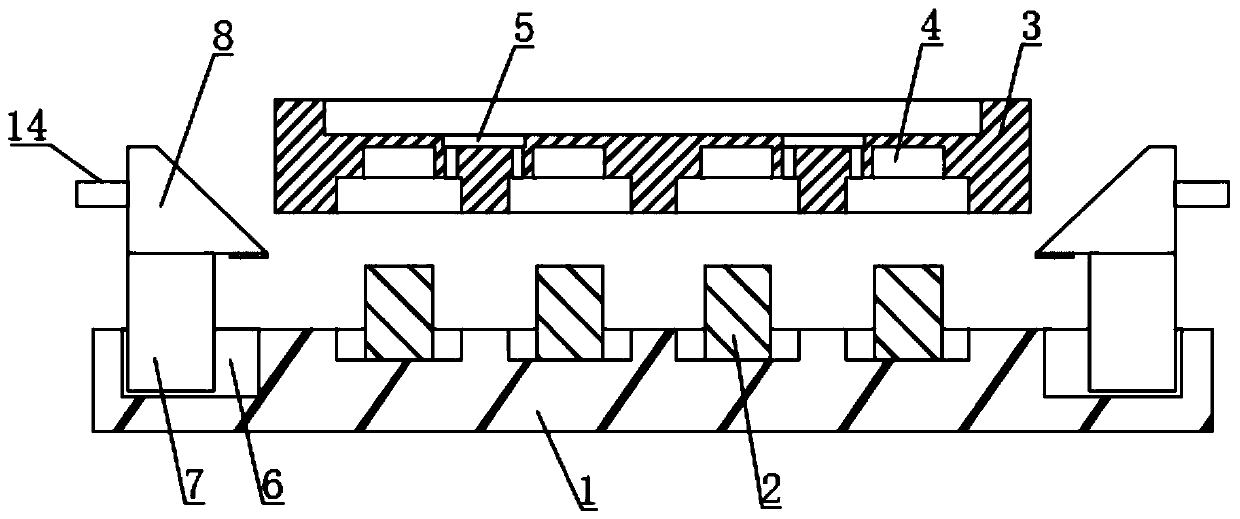
[0034] see figure 1 , a positionable O-ring mold, including a lower film 1 and an upper mold 3 each provided with a plurality of cavities, the upper mold 3 is located on the lower side of the lower film 1, and the upper end of the upper mold 3 is dug with a plurality of casting ports 5, see figure 2 with image 3 , a single casting port 5 is located between a pair of adjacent mold cavities, and a pair of mold cavities communicate with the casting port 5, and the slurry is injected into the closed cavity formed by the lower film 1 and the upper mold 3 through the casting port 5, and the lower A core 2 is provided inside the cavity of the film 1, and a limiting groove 4 is dug on the top surface of the cavity of the upper mold 3, and the core 2 matches the limiting groove 4. Compared with the prior art, four guide pillars are used to carry out In the way of positioning, the present invention can make the positioning of the lower film 1 and the upper mold 3 more accurate and s...


PUM


Abstract

The invention discloses an O-shaped ring die capable of being positioned, and belongs to the field of dies. The O-shaped ring die capable of being positioned comprises a lower die body and an upper die body, wherein the lower die body is provided with a plurality of cavities, and the upper die body is also provided with a plurality of cavities. A plurality of casting openings are drilled in the upper end of the upper die body. Cores are arranged in the cavities of the lower die body. Limiting grooves are drilled in the inner top surfaces of the cavities of the upper die body, and the cores arematched with the limiting grooves. Main sliding plates and pressing plates are separately arranged on the left side and the right side of the upper die body. The upper ends of the main sliding platesare fixedly connected with the lower ends of the pressing plates. A pair of main sliding grooves is drilled in the upper end of the lower die body. The lower ends of the main sliding plates are slidably connected into the main sliding grooves. Auxiliary sliding plates are arranged on the two sides of the main sliding plates. A plurality of auxiliary sliding grooves are drilled in the upper end ofthe lower die body. The lower ends of the auxiliary sliding plates are slidably connected into the auxiliary sliding plates. A pair of extension springs is fixedly connected between the upper end ofeach auxiliary sliding plate and the lower end of the corresponding pressing plate. According to the O-shaped ring die capable of being positioned, the lower die body and the upper die body can be tightly matched, positioning is stable, looseness is avoided in the using process, and the casting process can proceed smoothly.

Description

technical field [0001] The invention relates to the field of molds, and more specifically relates to a positionable O-ring mold. Background technique [0002] In the mold industry, various molds and tools are used for injection molding, blow molding, extrusion, die-casting or forging forming, smelting, stamping and other methods to obtain the required products. The O-ring mold is a kind of mold, but the existing O-ring mold The structure of the ring mold is relatively simple. The existing O-ring mold is only positioned by four guide posts and guide sleeves, and needs to be fed with an aluminum feeder. [0003] The existing O-ring molds are prone to loosening and unstable positioning during matching and positioning, thereby affecting the casting process. Contents of the invention [0004] 1. Technical problems to be solved [0005] In view of the problems existing in the prior art, the purpose of the present invention is to provide a positionable O-ring mold, which can re...

Claims


Application Information

Patent Timeline
IPC IPC(8): B29C39/26B29C39/22
CPCB29C39/22B29C39/26
Inventor 刘华刘桂艳刘亮
Owner 苏州钧固精密模具有限公司
Learn More