Al technical title is built by PatSnap Al team. It summarizes the technical point description of the patent document.
A flat mop and mop head technology, which is applied in the direction of cleaning floors, carpets, cleaning equipment, etc., can solve the problems of laborious and time-consuming assembly methods, inability to perform comprehensive cleaning, and insufficient mop handle length, and achieve compact structure, convenient mop dehydration, good connection effect
Active Publication Date: 2019-12-20
芜湖立新清洁用品有限公司
View PDF5 Cites 0 Cited by
Summary
Abstract
Description
Claims
Application Information
AI Technical Summary
This helps you quickly interpret patents by identifying the three key elements:
Problems solved by technology
Method used
Benefits of technology
Problems solved by technology
Now the handle length of a large proportion of flat mops is fixed and cannot be changed. According to different users and occasions, such as under the bed, under the furniture, and at corners, the length of the mop handle is often insufficient and cannot be used comprehensively. Cleanliness will affect the overall environmental sanitation in the long run
Therefore, there is a mop with a multi-section mop rod that can be adjusted in length. The multi-section mop rods are connected by a lock sleeve. However, the assembly process of this mop is relatively complicated. The handle is fixed, such an assembly method is laborious and time-consuming, so there is a need for a flat mop that improves the assembly method of the multi-section handle and simplifies the assembly process
Method used
Image
Click on the blue label to locate the original text in one second.
Reading with bidirectional positioning of images and text.
Examples
Embodiment Construction
[0029] In order to make the technical means, creative features, objectives and effects of the present invention easy to understand, the present invention will be further explained below in conjunction with specific embodiments.
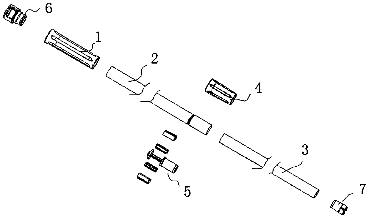
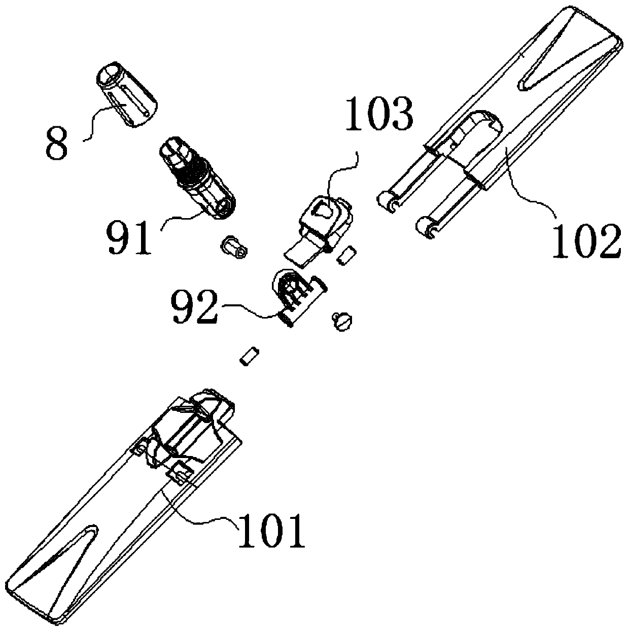
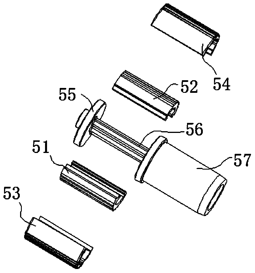
[0030] As an embodiment, the present invention provides a flat mop that includes a mop head and a mop rod connected to one end of the mop head. The mop rod includes a handle, a first connecting rod, a second connecting rod, and a lock sleeve. The handle, the first connecting rod, the locking sleeve, and the second connecting rod are sequentially sleeved and connected into one body, one end of the second connecting rod is connected with the mop head, and a self-locking device is provided inside the locking sleeve, One end of the self-locking device is sleeved in the first connecting rod, and the other end of the self-locking device is sleeved in the second connecting rod.
[0031] Through the design of the flat mop, the structure is simple and compact, and ...
PUM
Abstract
The invention discloses a horizontal plate mop, and relates to the field of cleaning tools. The horizontal plate mop comprises a mop head and a mop rod, wherein the mop head and the mop rod are connected, the mop rod comprises a handle, a first connecting rod, a second connecting rod and a locking sleeve, the handle, the first connecting rod, the locking sleeve and the second connecting rod are sequentially connected through sleeving into a whole, one end of the second connecting rod is connected with the mop head, a self-locking device is arranged in the locking sleeve, one end of the self-locking device sleeves in the first connecting rod, and the other end of the self-locking device sleeves in the second connecting rod. The horizontal plate mop is simple and compact in structure, and good in connecting effect, length adjustment can be carried out according to use occasions, during use, the mop rod can not have section separation, in addition, the mop can adapt to the cleaning requirements of different positions, the dead corners of sanitation are avoided, moreover, the self-locking device is slightly screwed through the locking sleeve, then the tight locking of the self-lockingdevice is completed, the mop rod then can be rapidly assembled, and the assembly process is simple.
Description
Technical field [0001] The invention relates to the technical field of cleaning appliances, in particular to a flat mop. Background technique [0002] The flat mop is a kind of sanitary ware used for daily cleaning. It is favored by consumers due to its high cleaning efficiency, strong detergency and convenient use. Nowadays, a large proportion of flat mops have fixed handle lengths and cannot be changed. According to different users and occasions, such as bed bottom, furniture, corners, the mop handle is not long enough to be comprehensive. Cleanliness will affect the overall environmental hygiene in the long term. Therefore, there is a mop with a multi-section mop rod that can be adjusted in length. The multi-section mop rods are connected by a lock sleeve. However, the assembly process of this mop is more complicated. The lock sleeve needs to be fully tightened to connect the upper and lower sections. The handle is fixed, and this assembly method is laborious and time consum...
Claims
Application Information
Patent Timeline
Application Date:The date an application was filed.
Publication Date:The date a patent or application was officially published.
First Publication Date:The earliest publication date of a patent with the same application number.
Issue Date:Publication date of the patent grant document.
PCT Entry Date:The Entry date of PCT National Phase.
Estimated Expiry Date:The statutory expiry date of a patent right according to the Patent Law, and it is the longest term of protection that the patent right can achieve without the termination of the patent right due to other reasons(Term extension factor has been taken into account ).
Invalid Date:Actual expiry date is based on effective date or publication date of legal transaction data of invalid patent.