
Semiconductor structures and methods of forming them

A semiconductor and isolation structure technology, applied in the field of semiconductor structure and its formation, can solve problems such as poor device performance, achieve the effect of improving device performance and avoiding loss

Active Publication Date: 2021-11-09
SEMICON MFG INT (SHANGHAI) CORP +1
View PDF12 Cites 0 Cited by
  • Summary
  • Abstract
  • Description
  • Claims
  • Application Information

AI Technical Summary

Problems solved by technology

[0004] However, after introducing the work function layer, the formed device still has the problem of poor performance

Method used

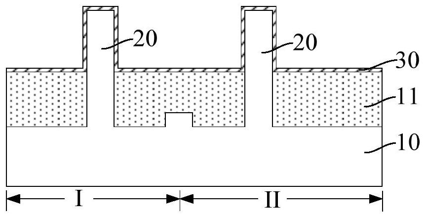
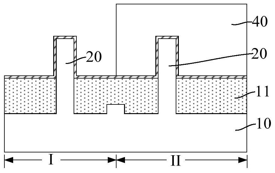
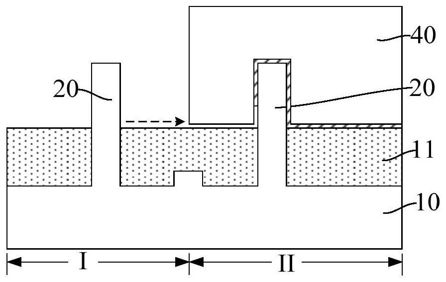

Image

  • Semiconductor structures and methods of forming them
  • Semiconductor structures and methods of forming them
  • Semiconductor structures and methods of forming them

Examples


Embodiment Construction

[0014] It can be seen from the background art that after introducing the work function layer, the formed device still has the problem of poor performance. The reasons for the poor performance of the device are analyzed in conjunction with a method of forming a semiconductor structure.

[0015] refer to Figure 1 to Figure 3 , shows a structural schematic diagram corresponding to each step in a method for forming a semiconductor structure.

[0016] refer to figure 1 , forming a base (not marked), the base includes a substrate 10 and fins 20 protruding from the substrate 10, the substrate 10 includes adjacent NMOS regions I and PMOS regions II, and the NMOS regions I is used to form a pull-down (PD, Pull Down) transistor, and the PMOS region II is used to form a pull-up (PU, Pull Up) transistor.

[0017] continue to refer figure 1 , forming an isolation structure 11 on the substrate 10 exposed by the fin portion 20, the isolation structure 11 covers part of the sidewall of ...


PUM

PropertyMeasurementUnit
widthaaaaaaaaaa

Abstract

A semiconductor structure and a method for forming the same, the method comprising: forming a base, the base includes a substrate and a plurality of first fins protruding from the substrate, the substrate includes an adjacent first region and a second region, the first region and the second region are used to form different types of transistors; a dummy fin is formed on the substrate at the junction of the first region and the second region; a first work function layer is formed across the first fin and the dummy fin, the second A work function layer covers part of the sidewall and part of the top of the first fin and the dummy fin; the first work function layer in the first region is removed by a wet etching process. Compared with the scheme in which no dummy fins are formed on the substrate at the junction of the first region and the second region, the dummy fins of the present invention prolong the path for the etching solution to diffuse to the first fins in the second region, which can gradually weaken the The degree of diffusion of the etching solution can prevent the loss of the first work function layer on the first fin in the second region, which is beneficial to improve the performance of the device.

Description

technical field [0001] The invention relates to the field of semiconductor manufacturing, in particular to a semiconductor structure and a forming method thereof. Background technique [0002] A Complementary Metal-Oxide Semiconductor (CMOS) device is one of the basic semiconductor devices constituting an integrated circuit. With the rapid development of integrated circuit manufacturing technology, the feature size of CMOS devices is always shrinking according to a certain ratio. It is a trend in the development of integrated circuits to replace the traditional oxide material gate dielectric layer with high-k material gate dielectric layer. . However, there are still many problems to be solved when forming a metal gate on a high-k gate dielectric layer, one of which is the matching of work function. Because the work function will directly affect the threshold voltage (Threshold Voltage) and device performance of the device, the work function must be adjusted to the appropr...

Claims


Application Information

Patent Timeline
Patent Type & Authority Patents(China)
IPC IPC(8): H01L21/8238H01L21/8244H01L27/092H01L27/11
CPCH01L21/823807H01L27/0924H10B99/00H10B10/12
Inventor 周飞
Owner SEMICON MFG INT (SHANGHAI) CORP
Learn More