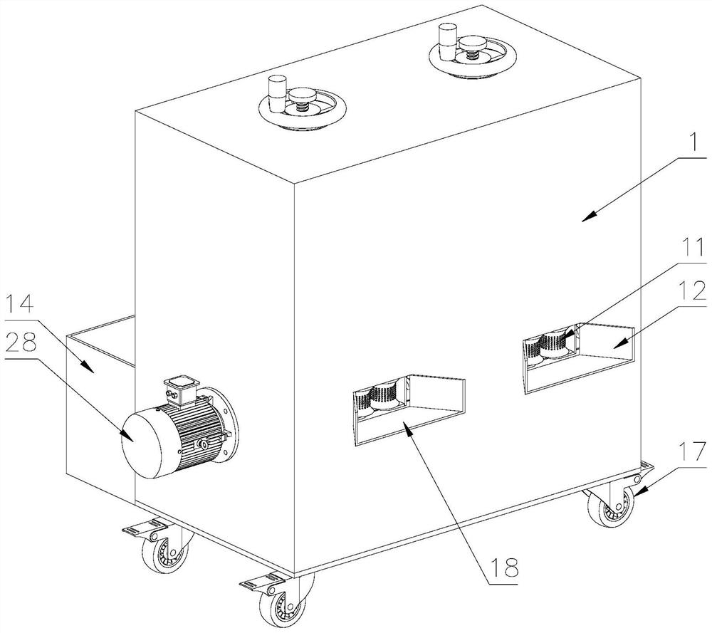
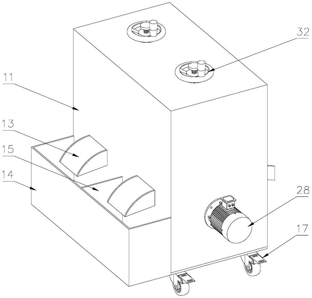
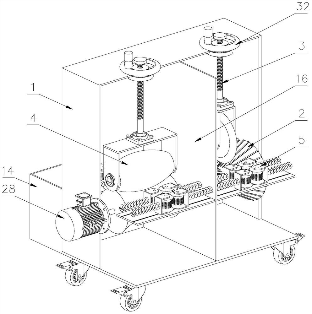
A waste cable peeling and recycling device

A recycling device and waste cable technology, applied in the field of electric power equipment, can solve the problems of time-consuming and laborious stripping, knife stabbing, difficult to be decomposed, etc., to achieve the effect of ensuring accuracy, increasing extrusion force, and ensuring cleanliness

Active Publication Date: 2021-02-19
RES INST OF ECONOMICS & TECH STATE GRID SHANDONG ELECTRIC POWER +1
View PDF10 Cites 0 Cited by
  • Summary
  • Abstract
  • Description
  • Claims
  • Application Information

AI Technical Summary

Problems solved by technology

[0002] Cable is a medium for long-distance transmission of electricity, and it can be seen everywhere. When a large number of cables are erected and used, when houses are demolished or cables are aged and replaced, a large number of discarded cables are bound to be removed, because the outside of the cable is covered with a soft plastic shell. The interior is equipped with copper wire cores. If a large number of discarded cables are discarded everywhere in the natural environment, it is difficult to be decomposed, which will cause environmental pollution.
If waste cables are recycled, stripped, and core-pulled, resources can be recycled. At present, the way to recycle waste cables is to manually use scissors and knives to manually strip the cables and pull the core. However, the specifications of the cables are different. For thicker cables If you use a knife to manually strip the wire, it will be time-consuming and laborious and difficult to strip the wire. If you strip the thinner cable manually, it may be because the cable is too thin. low line efficiency

Method used


Image

  • A waste cable peeling and recycling device
  • A waste cable peeling and recycling device
  • A waste cable peeling and recycling device

Examples


Embodiment Construction

[0035] Attached below Figure 1-7 , clearly and completely describe the technical solutions in the embodiments of the present invention, obviously, the described embodiments are only some of the embodiments of the present invention, not all of them. Based on the embodiments of the present invention, all other embodiments obtained by persons of ordinary skill in the art without making creative efforts belong to the protection scope of the present invention.

[0036] In describing the present invention, it should be understood that the terms "longitudinal", "transverse", "upper", "lower", "front", "rear", "left", "right", "vertical", The orientations or positional relationships indicated by "horizontal", "top", "bottom", "inner", "outer", etc. are based on the orientations or positional relationships shown in the drawings, and are only for the convenience of describing the present invention, rather than indicating or It should not be construed as limiting the invention by imply...


PUM


Abstract

The invention discloses a waste cable peeling recovery device. A moving wheel is arranged on one side of the lower part of the casing, a wire inlet guide plate is arranged on one side of the first wire inlet, and a first wire outlet is arranged on the other side of the casing; a first rotating shaft Both ends are movably installed on the housing through bearings, the output shaft of the motor is fixedly connected with the first rotating shaft; the first roller is arranged on the first rotating shaft, the cutting wheel is arranged on the upper part of the first roller, and the cutting wheel is provided with The second rotating shaft, both ends of the second rotating shaft are movably installed on the first bracket through bearings, the first connecting rod is arranged on the upper side of the first bracket, the upper end of the first connecting rod is connected with the housing, and the cable is arranged on the first roller and the cutting wheel, and the distance between the cutting edge of the cutting wheel and the first roller is smaller than the diameter of the cable. In the present invention, a skin-cutting device is provided inside the casing, the cable is placed on the first roller, and the plastic skin of the cable is cut by a cutting wheel, which avoids manual cutting with a knife, ensures the safety of the operator, and improves the safety of the cable. Peeling efficiency.

Description

technical field [0001] The invention belongs to the technical field of electric power equipment, in particular to a device for stripping and recovering waste cables. Background technique [0002] Cable is a medium for long-distance transmission of electricity, and it can be seen everywhere. When a large number of cables are erected and used, when houses are demolished or cables are aged and replaced, a large number of discarded cables are bound to be removed, because the outside of the cable is covered with a soft plastic shell. The interior is equipped with copper wire cores. If a large number of discarded cables are discarded everywhere in the natural environment and are difficult to be decomposed, it will cause environmental pollution. If waste cables are recycled, stripped, and core-pulled, resources can be recycled. At present, the way to recycle waste cables is to manually use scissors and knives to manually strip the cables and pull the core. However, the specificatio...

Claims


Application Information

Patent Timeline
Patent Type & Authority Patents(China)
IPC IPC(8): H01B15/00
CPCH01B15/00H01B15/006H01B15/008Y02W30/82
Inventor 孔德秋张丞王勇赵龙常英贤焦洋王艳郑志杰袁宝陈剑飞王振坤孙强张浩李菁竹毕晓伟付振霄牛华忠朱毅赵鹏飞钟乘鹏刘范范孔倩张翠珍乔亚男马丽苏静华赵娜康澍雨杨波胡恒瑞刘媛媛黄茗云李彦王庥祺孔儒刘小伟毕晓涛王萌张莞钰
Owner RES INST OF ECONOMICS & TECH STATE GRID SHANDONG ELECTRIC POWER
Why Eureka
Try Eureka