Trajectory planning method and system for remote control
A technology of trajectory planning and remote control, applied in the directions of measuring devices, instruments, surveying and navigation, etc., to achieve the effect of improving traffic efficiency
- Summary
- Abstract
- Description
- Claims
- Application Information
AI Technical Summary
Problems solved by technology
Method used
Image
Examples
Embodiment 1
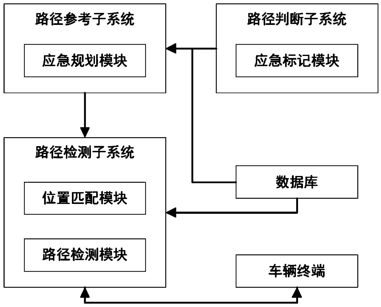
[0038] Trajectory planning system for remote control, as attached figure 1 As shown, it includes a path judgment subsystem, a path reference subsystem, a path detection subsystem, a vehicle terminal, and a database. The database is preset with a national map, a distance threshold, and a planned path. The planned path can be generated by an existing navigation system. After the navigation system generates the planned path, it can be stored in the database or directly sent to the path judgment subsystem. In this embodiment, the existing navigation system generates the planned path After that, the planned path is directly sent to the path judgment subsystem. The use of a navigation system to generate a planned route belongs to the prior art, so details will not be repeated here.
[0039] Path judgment subsystem, including:
[0040] The emergency marking module is used to receive the planned path. The planned path includes the starting point and the ending point of the path. The p...
Embodiment 2
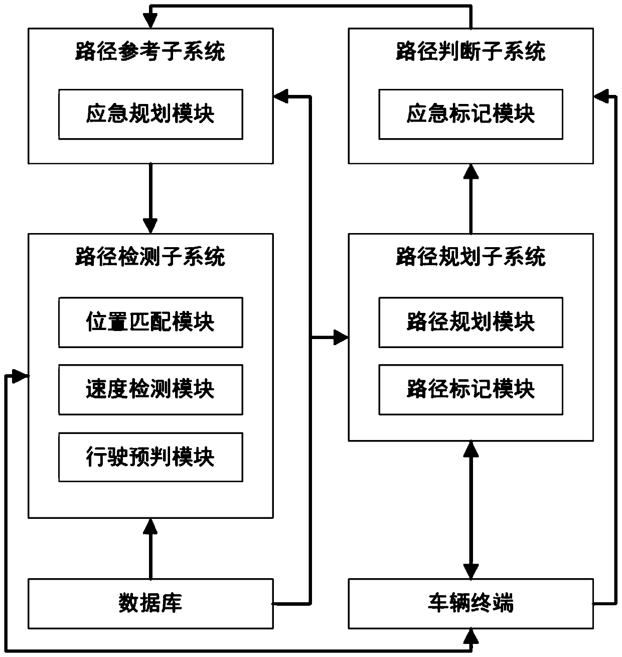
[0059] The difference between this embodiment and Embodiment 1 is that this embodiment is used for the trajectory planning system of remote control, as attached figure 2 As shown, the path planning subsystem is also included. The path detection subsystem also includes a speed detection module and a driving prediction module.
[0060] The vehicle terminal is used to obtain the starting point and end point of the route specified by the driver, and send the starting point and end point of the route to the path planning subsystem.
[0061] Path planning subsystem, including:
[0062] The path planning module is used to receive the path starting point and the path end point, obtain the national map from the database, and generate several planning paths according to the path starting point, path end point and the national map.
[0063] The route marking module is used to detect the planned route through the Internet of Vehicles technology, mark the section of the planned route wh...
Embodiment 3
[0083] The difference between this embodiment and Embodiment 2 is that in this embodiment, the trajectory planning system for remote control also includes a detection terminal.
[0084] Detection terminals include:
[0085] The first detection assembly includes a first detector, a second detector and a first controller. The first detector and the second detector are respectively installed on the upper end connection ring and the lower end connection ring of the automobile shock absorber. The first control The detector is used to calculate the relative distance between the first detector and the second detector according to the signals of the first detector and the second detector, calculate the distance difference according to the adjacent relative distance, and generate Jitter factor. In this embodiment, the first detector and the second detector are preferably the transmitting end and the receiving end of the laser ranging, and the transmitting end of the laser ranging is i...
PUM
 Abstract
Description
Claims
Application Information
 - Generate Ideas
- Intellectual Property
- Life Sciences
- Materials
- Tech Scout
- Unparalleled Data Quality
- Higher Quality Content
- 60% Fewer Hallucinations
Browse by: Latest US Patents, China's latest patents, Technical Efficacy Thesaurus, Application Domain, Technology Topic, Popular Technical Reports.
© 2025 PatSnap. All rights reserved.Legal|Privacy policy|Modern Slavery Act Transparency Statement|Sitemap|About US| Contact US: help@patsnap.com


