Eureka AIR delivers breakthrough ideas for toughest innovation challenges, trusted by R&D personnel around the world.

Pressure-adjustable clamping robot

A robot and pressure technology, applied in the direction of chucks, manipulators, manufacturing tools, etc., can solve the problems of clamping failure, easy clamping, and damage to carton packaging, so as to improve reliability and avoid excessive force on the clamped object. Damage and load-reducing effect

Active Publication Date: 2019-12-17
HENAN INST OF ENG
View PDF5 Cites 20 Cited by
  • Summary
  • Abstract
  • Description
  • Claims
  • Application Information

AI Technical Summary

Problems solved by technology

[0002] In the process of assembly line production and processing, in order to complete different processes, it is usually necessary to transfer industrial products from one production line to another by manual labor or clamping robots. The efficiency of manual transfer of products is low, and the cost of labor is high. Using Although the robot can greatly improve the efficiency, but the robot clamps and transfers the products, especially when the production is completed, the products that have been packed in cartons. If the clamping force is too strong, it is easy to damage the carton packaging or even damage the products. If the robot If the clamping force is too small, the clamping force may not be firm enough to cause clamping failure. Therefore, the scope of use of clamping robots is still limited. In order to further improve industrial production efficiency, it is necessary to specially design a non-destructive carton with adjustable pressure but clamping Robust Gripping Robot

Method used


Image

  • Pressure-adjustable clamping robot
  • Pressure-adjustable clamping robot
  • Pressure-adjustable clamping robot

Examples


Embodiment Construction

[0020] The technical solutions in the embodiments of the present invention will be clearly and completely described below in conjunction with the accompanying drawings in the embodiments of the present invention. Obviously, the described embodiments are only some of the embodiments of the present invention, not all of them. Based on The embodiments of the present invention and all other embodiments obtained by persons of ordinary skill in the art without making creative efforts belong to the protection scope of the present invention.

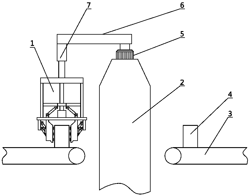
[0021] see Figure 1-7 , the present invention provides a technical solution: a clamping robot with adjustable pressure, including a manipulator 1, a machine body 2, and a conveyor belt 3, the left and right sides of the machine body 2 are provided with conveyor belts 3, and the conveyor belt on the left side of the machine body 2 The clamping object 4 placed on the top 3 is clamped and transferred to the conveyor belt 3 on the right side of the...


PUM


Abstract

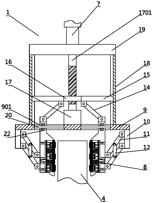
The invention discloses a pressure-adjustable clamping robot. Clamped objects placed on a left side conveying belt of a machine main body of the clamping robot are transferred onto a right side conveying belt of the machine main body through manipulator clamping; a rotating shaft of a rotating motor at the upper end of the machine main body is fixedly connected with the lower side of one end of across beam; and the lower side of the other end of the cross beam is fixedly connected with a manipulator through a lifter. The manipulator clamps the clamped objects through a rotating motor drivingclamping plates to move; in the moving process of the clamping plates, a driving gear is rotated under the effect of a lead screw, and is in transmission connection with a guide wheel through a drivengear and a conveying belt; in the rotating process of a third lead screw, the third lead screw drives a piston to move to extract air in a sucker; the clamped objects are absorbed by using a suctioneffect of the sucker to prevent damage of the clamped objects caused by direct clamping through first slide plates; when heavier clamped objects are clamped, the sucker can be hidden through the position adjustment of the first slide plates by adjusting bolts; and the clamped objects are directly clamped by using the first slide plates.

Description

technical field [0001] The invention belongs to the technical field of industrial machinery and equipment, in particular to a clamping robot with adjustable pressure. Background technique [0002] In the process of assembly line production and processing, in order to complete different processes, it is usually necessary to transfer industrial products from one production line to another by manual labor or clamping robots. The efficiency of manual transfer of products is low, and the cost of labor is high. Using Although the robot can greatly improve the efficiency, but the robot clamps and transfers the products, especially when the production is completed, the products that have been packed in cartons. If the clamping force is too strong, it is easy to damage the carton packaging or even damage the products. If the robot If the clamping force is too small, the clamping force may not be firm enough to cause clamping failure. Therefore, the scope of use of clamping robots is ...

Claims


Application Information

Patent Timeline
Patent Type & Authority Applications(China)
IPC IPC(8): B25J15/08B25J15/02
CPCB25J15/08B25J15/0253Y02P70/50
Inventor 李坤全文睿刘旭贺邵凤翔李辉朱谧浩王博刘艳龙
Owner HENAN INST OF ENG
Why Eureka
Eureka Blog
Learn More