
Contact piece riveting tool and riveting method

A technology for riveting tools and contacts, which is applied in the direction of manufacturing tools, connections, electrical components, etc., can solve the problems of affecting the use cost of devices, reducing work efficiency, and scrapping contacts, so as to improve riveting quality, improve work efficiency, and reduce circulation when the effect

Pending Publication Date: 2019-12-17
ZIYANG CHENFENG ELECTRIC
View PDF0 Cites 1 Cited by
  • Summary
  • Abstract
  • Description
  • Claims
  • Application Information

AI Technical Summary

Problems solved by technology

In the prior art, riveting is mainly carried out by manual hammering. This method is likely to cause incomplete riveting or deflection during the riveting process, causing a large number of contact parts to be scrapped.
Among them, insufficient riveting will cause inevitable safety hazards in the subsequent use of the contacts, and a large number of scrapped riveted contacts will affect the use cost of the device and reduce work efficiency

Method used


Image

  • Contact piece riveting tool and riveting method
  • Contact piece riveting tool and riveting method
  • Contact piece riveting tool and riveting method

Examples


Embodiment 1

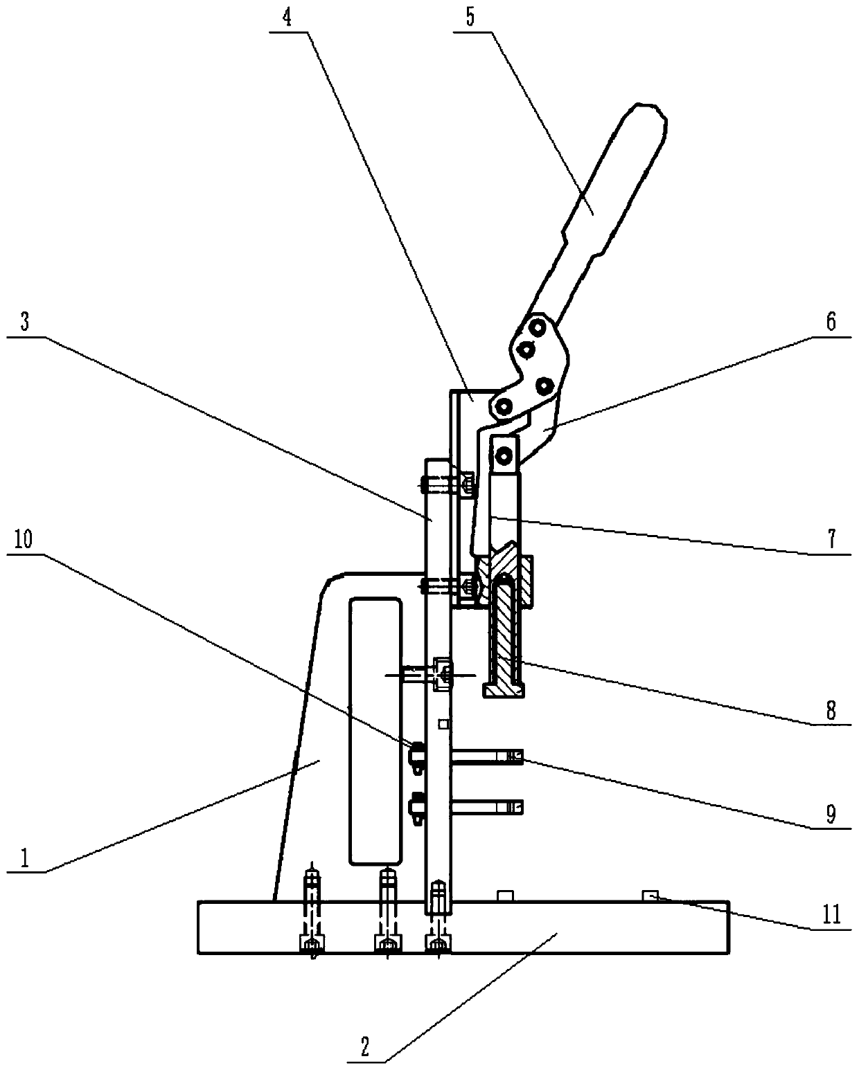
[0032] A contact riveting tool, including a riveting module and a base; such as figure 1 As shown, the pressure riveting module includes a handle 1, a horizontal fixing plate 2 and a vertical fixing plate 3, the handle 1 is fixed to the horizontal fixing plate 2 by bolts, and the vertical fixing plate 3 is fixed to the handle 1 by bolts. side. The upper part of the vertical fixed plate 3 is equipped with a fixture, and the clamp includes a mounting seat 4, a handle 5, a linkage rod 6 and a lower pressure rod 7, and the mounting seat 4 is fixed on the vertical fixed plate 3 by bolts. One end of the handle 5 is hinged to the upper part of the mounting base 4, and the other end is in transmission connection with the lower pressing rod 7 through the linkage rod 6. The lower pressing rod 7 is placed in the limit sleeve of the mounting base 4, and the lower pressing rod 7 The front end is provided with a detachable chuck 8; the bottom of the vertical fixing plate 3 has a hole, and ...

Embodiment 2

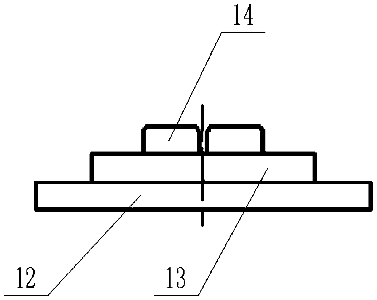
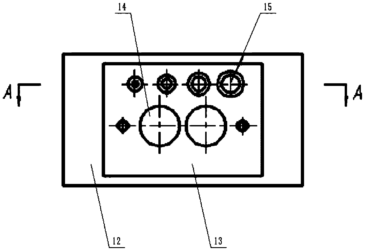
[0037] Such as Figure 6As shown, on the basis of Embodiment 1, positioning and fixing holes 24 are provided on the first base plate of the base, and positioning and fixing holes 24 are provided on the horizontal fixing plate of the pressure riveting module corresponding to the positions of different positioning protrusions and mounting holes on the base. The base can be fixed on the horizontal fixing plate through the bolt, and the positioning and fixing holes at different positions up and down are used to cooperate to ensure that the components to be riveted at different positions on the base correspond to the upper and lower sides of the chuck of the fixture.

[0038] Enables contact riveting to socket body such as figure 1 and Figure 7 As shown, first put the parts to be riveted into the riveting positioning tube 20, put the SMC protective sleeve 21, a certain type of contact point 22 and the socket body 23 into the riveting positioning tube 20 from top to bottom, and pl...


PUM


Abstract

The invention discloses a contact piece riveting tool and a riveting method. The tool comprises a pressing riveting module and a base. The pressing riveting module comprises a horizontal fixing plateand a vertical fixing plate mounted on the horizontal fixing plate. A clamp and limiting plates are mounted on the upper portion of the vertical fixing plate. The base comprises two layers of base plates. Mounting holes and auxiliary positioning protrusions are arranged on the base plates. During riveting, corresponding parts to be riveted are fixed to the base and the limiting plates correspondingly, the lower pressure is applied by the clamp, and successful riveting of the corresponding parts is achieved. The contact part riveting tool is simple in structure and convenient to operate and maintain; by using the base and the limiting plates with the positioning function, the stability of the parts in the horizontal direction during riveting is guaranteed, the riveting precision is guaranteed, the riveting quality is improved, and the riveting waste is not generated; and the tool is used for replacing manual hammer riveting, the hand-held pre-riveting link is reduced, the injury risk ofan operator is reduced, the time of circulation of parts among stations is shortened, the whole production time is shortened, and the working efficiency is improved.

Description

technical field [0001] The invention belongs to the field of electrical connectors, and in particular relates to a contact riveting tool and a riveting method. Background technique [0002] At present, electrical connectors are used in various industries, among which contacts are one of the key components of electrical connectors, and most signal contacts need to be riveted. In the prior art, the riveting is mainly carried out by manual hammering. This method is likely to cause the riveting not in place or to cause deflection during the riveting process, causing a large number of contact parts to be scrapped. Among them, insufficient riveting will cause inevitable safety hazards in the subsequent use of the contacts, and a large number of scrapped riveted contacts will affect the use cost of the device and reduce work efficiency. Contents of the invention [0003] The technical problem to be solved by the present invention is to provide a riveting tool for contact parts a...

Claims


Application Information

Patent Timeline
Patent Type & Authority Applications(China)
IPC IPC(8): B21D43/00B21D39/00H01R43/048H01R4/06
CPCB21D43/003B21D39/00H01R43/048H01R4/06
Inventor 聂山程张旭恩卿杰罗棚元董刚刚钟申强唐中彬崔涵
Owner ZIYANG CHENFENG ELECTRIC
Learn More