Eureka AIR delivers breakthrough ideas for toughest innovation challenges, trusted by R&D personnel around the world.

Alloy analysis visual positioning method, device, and alloy analysis system

A visual positioning and alloy analyzer technology, applied in the field of visual inspection, can solve the problems of low positioning efficiency and large calculation amount, and achieve the effects of improving accuracy and efficiency, reducing calculation amount, and high calculation and positioning efficiency

Active Publication Date: 2019-12-13
JIANGSU JINHENG INFORMATION TECH CO LTD
View PDF9 Cites 8 Cited by
  • Summary
  • Abstract
  • Description
  • Claims
  • Application Information

AI Technical Summary

Problems solved by technology

However, in the actual production process, the diameters of finished wire rods and coils vary widely, ranging from 5mm to 34mm and 1.2m to 1.5m respectively. When combining finished wire rods and coils of different specifications, it is necessary to photograph at least Three light bar raster images are used to calculate the phase value, resulting in a large amount of calculation and low positioning efficiency

Method used


Image

  • Alloy analysis visual positioning method, device, and alloy analysis system
  • Alloy analysis visual positioning method, device, and alloy analysis system
  • Alloy analysis visual positioning method, device, and alloy analysis system

Examples


Embodiment Construction

[0055] The technical solutions in the embodiments of the present invention will be clearly and completely described below in conjunction with the accompanying drawings in the embodiments of the present invention. Obviously, the described embodiments are only some, not all, embodiments of the present invention. Based on the embodiments of the present invention, all other embodiments obtained by persons of ordinary skill in the art without making creative efforts belong to the protection scope of the present invention.

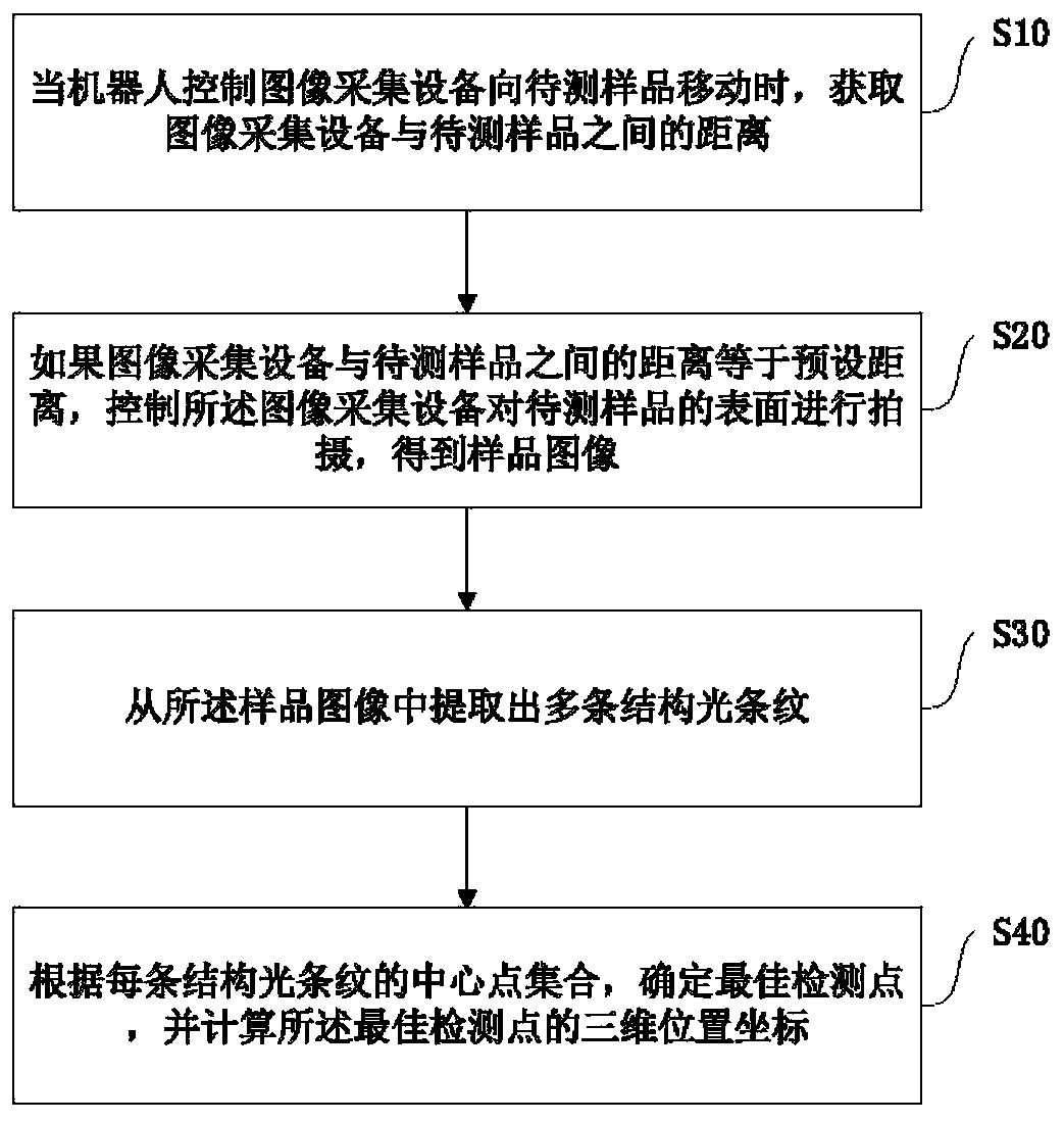
[0056] Such as figure 1 As shown, an embodiment of the present application provides a visual positioning method for alloy analysis, the method comprising:

[0057] Step S10, when the robot controls the image acquisition device to move towards the sample to be tested, obtain the distance between the image acquisition device and the sample to be tested; wherein, the image acquisition device is equipped with a structured light source.

[0058] Since this applicati...


PUM


Abstract

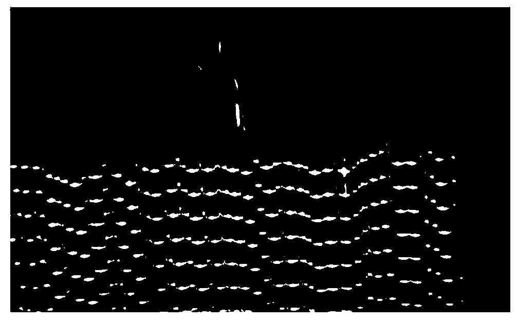
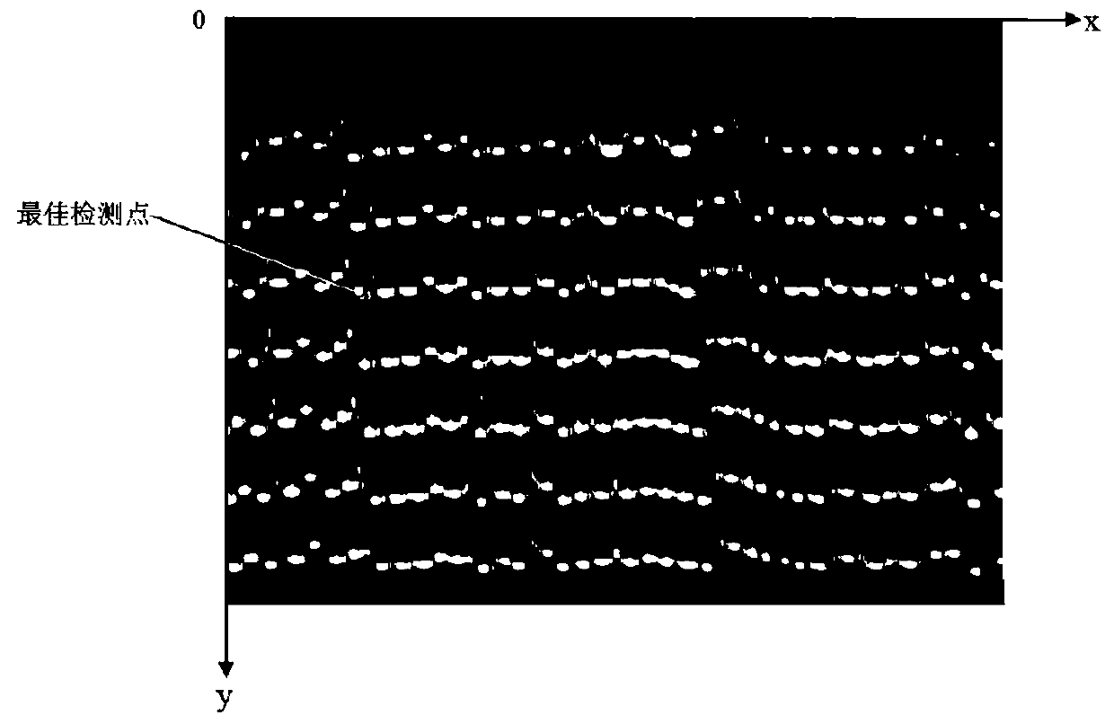
The invention discloses an alloy analysis visual positioning method, a device and an alloy analysis system. The method comprises the steps: obtaining the distance between image collection equipment and a to-be-detected sample when a robot controls the image collection equipment to move to the to-be-detected sample, wherein the image acquisition equipment is provided with a structure light source;if the distance between the image acquisition equipment and the to-be-detected sample is equal to the preset distance, controlling the image acquisition equipment to shoot the surface of the to-be-detected sample to obtain a sample image; extracting a plurality of structured light stripes from the sample image; determining an optimal detection point according to the central point set of each structured light stripe, and calculating three-dimensional position coordinates of the optimal detection point, wherein each central point set comprises other pixel points except the pixel points of the edge areas on the two sides in the corresponding structured light stripe. According to the method, the three-dimensional position coordinates of the optimal detection point can be calculated only by shooting one sample image in the detection area, the calculated amount is reduced, a complex image processing process is not needed, and the calculation and positioning efficiency is higher.

Description

technical field [0001] The present application relates to the technical field of visual inspection, in particular to a visual positioning method, device and alloy analysis system for alloy analysis. Background technique [0002] With the development of optics, computer and image processing technologies, optical non-contact measurement has the advantages of fast measurement speed and high measurement accuracy, and is widely used in various fields. For example, in the iron and steel industry, due to the diversification of products, its production level tends to be automated and refined. In order to prevent the mixing of different steel grades, it is necessary to analyze the alloy composition of the finished wire rod. [0003] In the analysis of alloys, the structured light measurement system is currently used to locate the best detection point on the sample surface. The structured light measurement system is mainly composed of a structured light projection device, a camera, an...

Claims


Application Information

Patent Timeline
Patent Type & Authority Applications(China)
IPC IPC(8): G01N21/84G01N21/01G01B11/25
CPCG01B11/002G01B11/254G01N21/01G01N21/84
Inventor 孙茂杰徐海宁张楠杨文苏循亮周鼎
Owner JIANGSU JINHENG INFORMATION TECH CO LTD
Why Eureka
Eureka Blog
Learn More