Road repairing device and repairing method

A road repair and width technology, applied in road repair, roads, roads, etc., can solve problems such as asphalt that cannot be adjusted to fill, and achieve the effect of even filling and avoiding blockage

Active Publication Date: 2021-04-16
济南通达公路工程有限公司
View PDF1 Cites 0 Cited by
  • Summary
  • Abstract
  • Description
  • Claims
  • Application Information

AI Technical Summary

Problems solved by technology

But the device cannot adjust the amount of asphalt filled according to the width of the road groove filled

Method used


Image

  • Road repairing device and repairing method
  • Road repairing device and repairing method
  • Road repairing device and repairing method

Examples


specific Embodiment approach 1

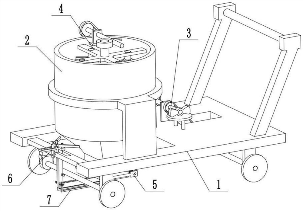
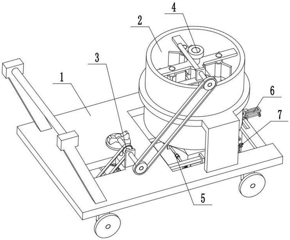
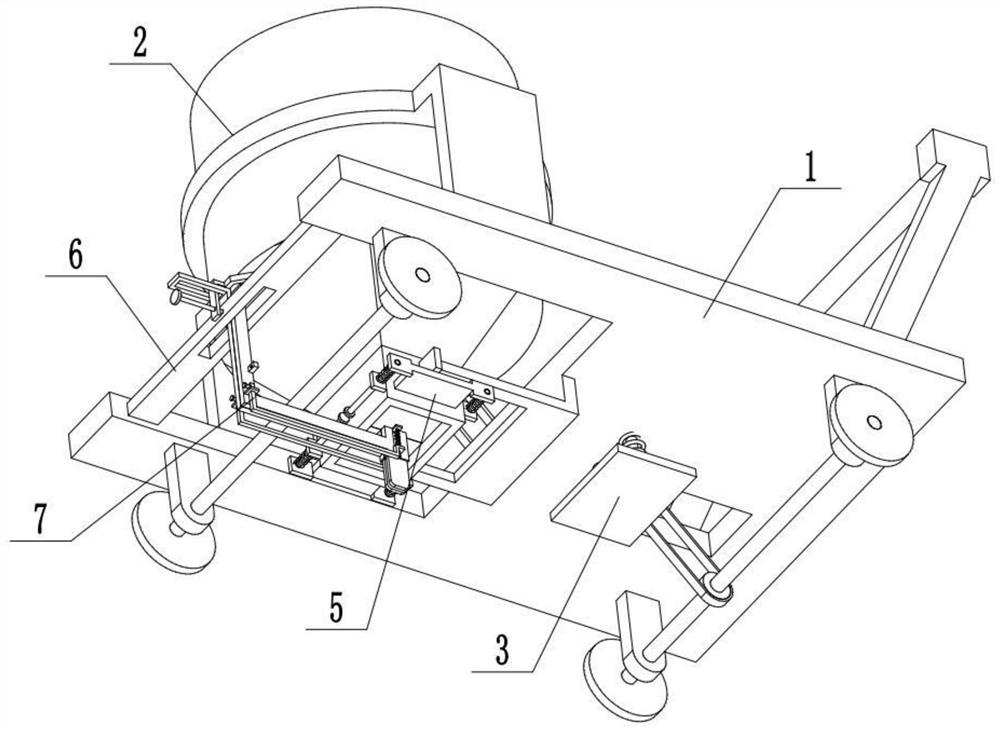
[0037] Combine below Figure 1-11 Describe this embodiment, a road repair device and repair method, including a mobile cart 1, an asphalt storage cylinder 2, a flattening mechanism 3, a stirring mechanism 4, a width-adaptive floor frame 5, a width locking mechanism 6 and a width-adaptive plate Component 7, the asphalt storage cylinder 2 is fixedly connected to the mobile cart 1, the flattening mechanism 3 is arranged on the right end of the asphalt storage cylinder 2, the flattening mechanism 3 is connected to the mobile cart 1 by transmission, and the mixing mechanism 4 is arranged on the asphalt On the storage cylinder 2, the stirring mechanism 4 is connected with the flattening mechanism 3, and two width-adaptive floor frames 5 are provided. Fixedly connected to the left end of the mobile cart 1, the left ends of the two width-adaptive floor frames 5 are slidingly fitted and connected to the width locking mechanism 6, and two width-adaptive board assemblies 7 are provided, ...

specific Embodiment approach 2

[0039] Combine below Figure 1-11 To illustrate this embodiment, the mobile trolley 1 includes a chassis plate 1-1, a trolley frame 1-2, a belt passing groove 1-3, a cylinder support frame 1-4, a roller shaft 1-5, and a shaft frame 1 -6, roller 1-7 and driving pulley 1-8; hand push frame 1-2 is fixedly connected to the right end of chassis plate 1-1, and belt is arranged on the chassis plate 1-1 through groove 1-3, and tube The support frame 1-4 is fixedly connected to the bottom surface of the chassis plate 1-1, and the two roller shafts 1-5 are respectively rotatably connected to the two shaft frames 1-6, and the two roller shafts 1-5 respectively pass through the two shaft frames 1-6 is fixedly connected to the left and right ends of the chassis plate 1-1, the two ends of the two roller shafts 1-5 are respectively fixedly connected to a roller 1-7, and the driving pulley 1-8 is fixedly connected to the right roller shaft 1-5, driving pulley 1-8 is connected with flattening...

specific Embodiment approach 3

[0041] Combine below Figure 1-11 To illustrate this embodiment, the asphalt storage cylinder 2 is fixedly connected to the cylinder frame 2-1, and the lower end of the asphalt storage cylinder 2 is symmetrically provided with two material baffle slides 2-2.


PUM


Abstract

A road repairing device and repairing method of the present invention, comprising: 1. separating the two width-adapting plate components from the ground and fixing the positions of the two width-adapting plate components; Push the cart to the gap to be filled on the road, and when the cart moves, it will drive the flattening mechanism to work, and the flattening mechanism will drive the mixing mechanism to mix the asphalt, so that the asphalt can be output smoothly; 3. Unscrew the two positioning screws and The two threaded hole seats are separated, and the two vertical side plates are protruded downward into the gully; 4. Adjust the width locking mechanism so that the width locking mechanism is separated from the two width-adaptive floor frames, and the two width-adaptive floor frames The outward expansion drives the two width-adaptive plate components to fit on the inner wall of the gully to be filled; 5. After the two width-adaptive plate components expand outward, the asphalt in the asphalt storage cylinder is discharged outward into the gully, and the moving pusher is slowly pushed The car gradually outputs the asphalt, and at the same time, the flattening mechanism flattens the asphalt.

Description

technical field [0001] The invention relates to the technical field of road maintenance, in particular to a road repairing device and a repairing method. Background technique [0002] The existing patent number is CN201910071323.2 for the road repair and crushing device. The invention belongs to the field of road equipment. It specifically discloses the road repair and crushing device, including a car body, a crushing mechanism located in the car body, a dust suction pump and a filling mechanism. The car body There is a lever inside, the vacuum pump and the filling mechanism are respectively fixedly connected to the two ends of the lever, the bottom of the lever on one side of the vacuum pump is fixedly connected with an elastic piece, and the vacuum pump is connected with a suction pipe for absorbing road gravel particles, and the suction pipe passes through The bottom of the car body and the mouth of the nozzle are facing the bottom of the car body; the filling mechanism i...

Claims


Application Information

Patent Timeline
Patent Type & Authority Patents(China)
IPC IPC(8): E01C23/09E01C19/10
CPCE01C19/104E01C23/0973
Inventor 杨雨
Owner 济南通达公路工程有限公司
Why Eureka
Try Eureka