
Steel-plastic composite pipe heating device

A steel-plastic composite pipe and heating device technology, which is applied to tubular objects, other household appliances, household appliances, etc., can solve the problems of high labor intensity for workers, overheating of inner pipes, time-consuming and labor-intensive problems, etc.

Pending Publication Date: 2019-12-13
安徽海通塑胶科技有限公司
View PDF0 Cites 0 Cited by
  • Summary
  • Abstract
  • Description
  • Claims
  • Application Information

AI Technical Summary

Problems solved by technology

[0002] The steel-plastic composite pipe is a galvanized internal plastic-coated composite steel pipe for water supply made by pretreatment, preheating, internal coating, leveling, and post-treatment processes. At present, steel-plastic composite pipes are mostly produced by winding steel wires on the inner pipe. After the steel mesh is formed, the adhesive is coated, and then the outer layer is compounded, that is, the production method of the outer pipe. This method needs to heat the inner pipe to make the steel mesh and the inner pipe bond together. The traditional heating method of the inner pipe is It is a manual hand-held clamp to clamp the inner tube and heat the inner tube. The manual heating method is time-consuming and labor-intensive. Working for a long time will bring greater labor intensity to the worker. In addition, this heating method is made by the worker. The tube is fixed to heat the inner tube, which will lead to uneven heating, local overheating of the inner tube, and poor adhesion between the inner tube and the steel wire mesh

Method used


Image

  • Steel-plastic composite pipe heating device
  • Steel-plastic composite pipe heating device
  • Steel-plastic composite pipe heating device

Examples


Embodiment Construction

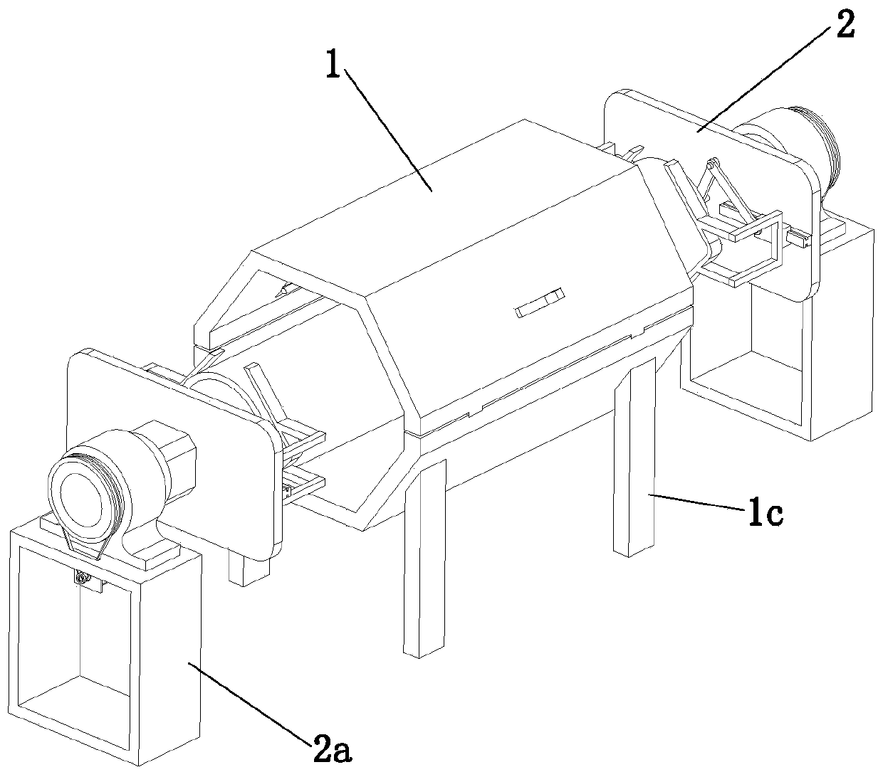
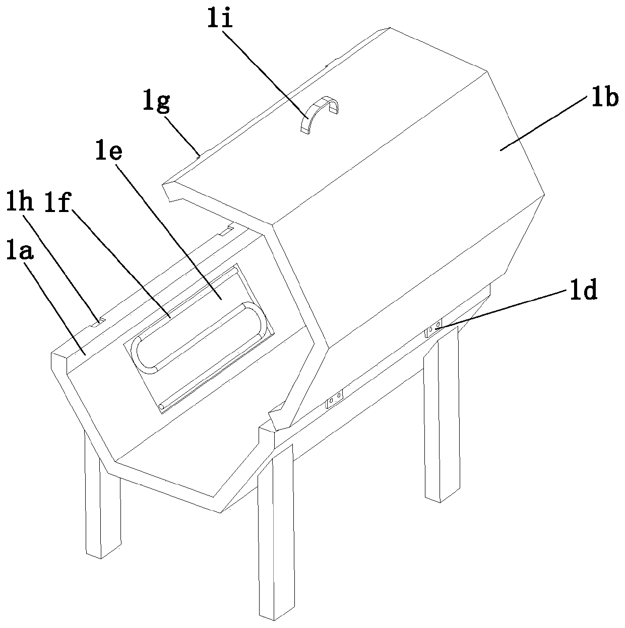
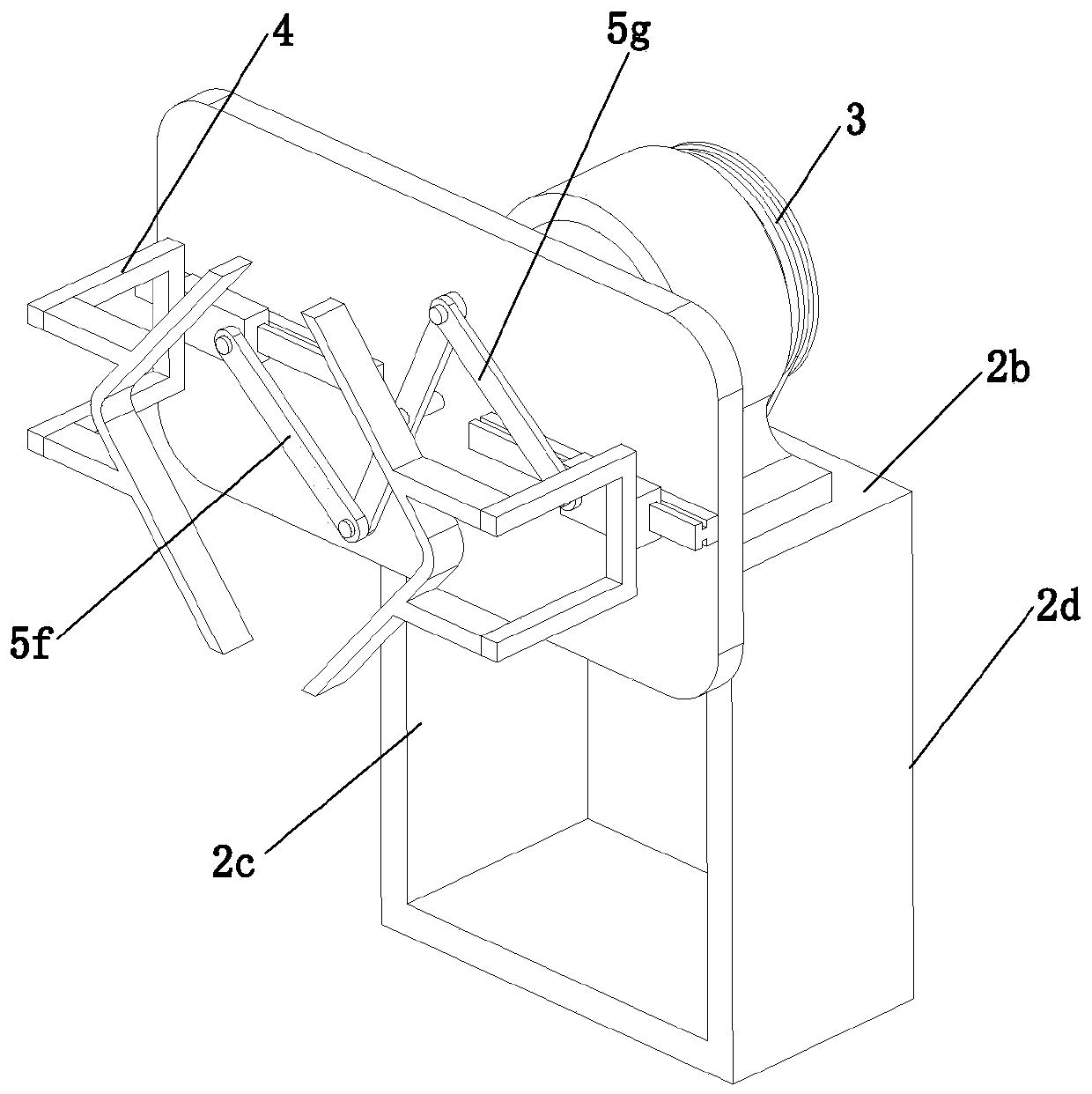
[0019] The following will be combined with Figure 1 to Figure 5 The present invention is described in detail, and the technical solutions in the embodiments of the present invention are clearly and completely described. Apparently, the described embodiments are only some of the embodiments of the present invention, not all of them. Based on the embodiments of the present invention, all other embodiments obtained by persons of ordinary skill in the art without making creative efforts belong to the protection scope of the present invention.

[0020] The present invention provides a steel-plastic composite pipe heating device through improvement, such as Figure 1-Figure 5 As shown, it includes a heating assembly 1 and two symmetrically arranged clamping assemblies 2. The heating assembly 1 is arranged between the two clamping assemblies 2. The heating assembly 1 includes a lower heating plate 1a and a lower heating plate 1a. The upper heating plate 1b on the top of the plate 1...


PUM


Abstract

The invention relates to the field of steel-plastic composite pipe machining equipment, in particular to a steel-plastic composite pipe heating device. A heating assembly and two symmetrically-arranged clamping assemblies are included. The heating assembly comprises a lower heating plate and an upper heating plate arranged on the top of the lower heating plate. Four supporting legs are arranged atthe bottom of the lower heating plate. The inner side wall of each of the upper heating plate and the lower heating plate is provided with two installing grooves. Each installing groove is internallyprovided with a heating pipe. The two clamping assemblies are the same in structure and each comprises a bearing frame, a rotation component and a clamping component. The steel-plastic composite pipeheating device has the beneficial effects that the two clamping assemblies can be used for clamping the two ends of an inner pipe, hand holding through manual hand operation is not needed, and the labor intensity of workers is lowered; and through the rotation components, the inner pipe of a plastic composite pipe can be rotated, the inner piper can slowly rotate, and the situation that due to uneven heating of the inner pipe, bonding with a steel wire gauze is poor is avoided.

Description

technical field [0001] The invention relates to the field of steel-plastic composite pipe processing equipment, in particular to a steel-plastic composite pipe heating device. Background technique [0002] The steel-plastic composite pipe is a galvanized internal plastic-coated composite steel pipe for water supply made by pretreatment, preheating, internal coating, leveling, and post-treatment processes. At present, steel-plastic composite pipes are mostly produced by winding steel wires on the inner pipe. After the steel mesh is formed, the adhesive is coated, and then the outer layer is compounded, that is, the production method of the outer pipe. This method needs to heat the inner pipe to make the steel mesh and the inner pipe bond together. The traditional heating method of the inner pipe is It is a manual hand-held clamp to clamp the inner tube and heat the inner tube. The manual heating method is time-consuming and labor-intensive. Working for a long time will bring ...

Claims


Application Information

Patent Timeline
Patent Type & Authority Applications(China)
IPC IPC(8): B29C65/78B29C65/02B29L23/00
CPCB29C65/7841B29C65/02B29C66/80B29C66/532B29L2023/22
Inventor 李智
Owner 安徽海通塑胶科技有限公司
Learn More