
A high-density component multi-stage blind insertion intelligent assembly device and blind insertion method

An assembly device and high-density technology, applied in metal processing equipment, metal processing, manufacturing tools, etc., can solve the problems of small pinholes of radio frequency connectors, high density of internal components, and limited space of radio frequency devices, so as to avoid two Second misalignment, ensure blind mating accuracy and connection reliability, and reduce the effect of human disturbance

Active Publication Date: 2020-08-28
CHINA ELECTRONIC TECH GRP CORP NO 38 RES INST
View PDF6 Cites 2 Cited by
  • Summary
  • Abstract
  • Description
  • Claims
  • Application Information

AI Technical Summary

Problems solved by technology

During the installation process, since the actual installation state of the connector cannot be observed and the pinhole of the RF connector is small (the diameter of the SMP connector is generally about 0.4mm), it is difficult for the operator to perceive the blind mating state of the blind mating connector, and the connector is prone to occur. If the needle is bent or even broken, the connector will be damaged and the radio frequency device will not work properly
In addition, under normal circumstances, the space of some radio frequency devices is limited, the arrangement density of internal components is high, and the installation and operation space of blind-mating connectors is narrow, which makes it difficult to install internal components and connectors, and the installation accuracy is difficult to guarantee, which affects the performance of the device

Method used


Image

  • A high-density component multi-stage blind insertion intelligent assembly device and blind insertion method
  • A high-density component multi-stage blind insertion intelligent assembly device and blind insertion method
  • A high-density component multi-stage blind insertion intelligent assembly device and blind insertion method

Examples


Embodiment Construction

[0026] The above and other technical features and advantages of the present invention will be described in more detail below in conjunction with the accompanying drawings.

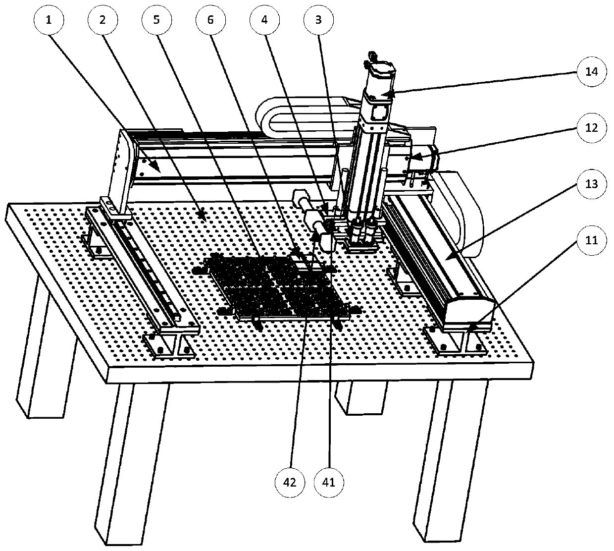
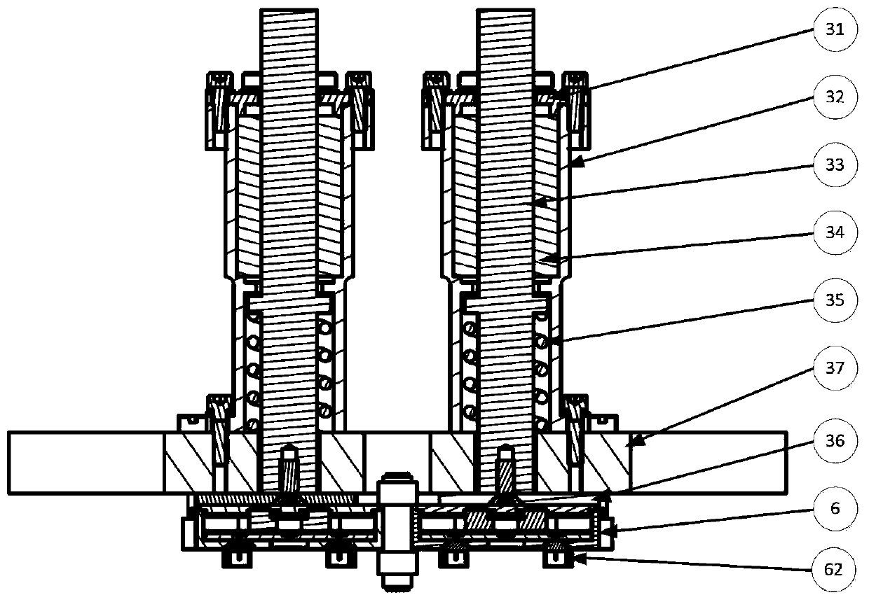
[0027] Such as figure 1 as shown, figure 1 It is a structural view of the intelligent assembly device for multi-level blind insertion of high-density components; the intelligent assembly device for multi-level blind insertion of high-density components in the present invention includes a three-dimensional servo motion platform 1, a precision optical platform 2, a TR component grabbing unit 3, The laser scanning unit 4, the three-dimensional servo motion platform 1 is installed on the precision optical platform 2, the TR component grabbing unit 3 and the laser scanning unit 4 are installed on the three-dimensional servo motion platform 1, so The three-dimensional servo motion platform 1 is used to control the movement of the TR component grasping unit 3 and the laser scanning unit 4 in three directions of ...


PUM


Abstract

The invention discloses a multi-stage blind mating intelligent assembly device for a high-density component and a blind mating method thereof. The device comprises a three-dimensional servo motion platform, a precision optical platform, a TR component grabbing unit and a laser scanning unit, wherein the three-dimensional servo motion platform is arranged on the precision optical platform, the TR component grabbing unit and the laser scanning unit are both arranged on the three-dimensional servo motion platform, and the three-dimensional servo motion platform is used for controlling the motionof the TR component grabbing unit and the laser scanning unit in the three-dimensional space; an antenna structure is placed on the precision optical platform, and the TR component grabbing unit grabsTR components and realizes the blind mating of the antenna structure and the TR components under the positioning of the laser scanning unit and the movement of the three-dimensional servo motion platform. According to the multi-stage blind mating intelligent assembly device for the high-density component and the blind mating method thereof, the position and depth of a blind mating hole position of a connector can be automatically detected, in the blind mating assembly process of the blind mating connector, the blind mating hole position detection and positioning of different platforms and different array face scales are adapted, and references are provided for the blind mating assembly process.

Description

technical field [0001] The invention relates to the technical field of intelligent assembly, in particular to an intelligent assembly device and blind insertion method for multi-stage blind insertion of high-density components. Background technique [0002] In a radio frequency device, the transmission of radio frequency signals between each unit usually relies on radio frequency connectors, such as the transmission of radio frequency signals between the TR component and the antenna unit. Limited by the space and weight inside the RF device, most connectors are connected by blind-mating interconnection, that is, the electrical connection point is located in a closed cavity and is invisible. At present, the installation of blind-mating connectors basically relies on manual blind-mating. During the installation process, since the actual installation state of the connector cannot be observed and the pinhole of the RF connector is small (the diameter of the SMP connector is gen...

Claims


Application Information

Patent Timeline
Patent Type & Authority Patents(China)
IPC IPC(8): B23P19/02B23P19/00
CPCB23P19/001B23P19/02
Inventor 陈崇斌王岩董好志孙晓伟王国超王志刚殷忠义杨婷婷
Owner CHINA ELECTRONIC TECH GRP CORP NO 38 RES INST
Learn More