
Contact mechanism of universal circuit breaker

A circuit breaker and universal technology, applied in the directions of circuit breaker contacts, circuit breaker parts, etc., can solve the problems of affecting the effective action of the spring force, contact spring damage, and current capacity increase, etc., to improve product safety performance, The effect of prolonging the service life and ensuring the normal operation

Active Publication Date: 2020-01-21
ZHEJIANG CHINT ELECTRIC CO LTD +1
View PDF5 Cites 0 Cited by
  • Summary
  • Abstract
  • Description
  • Claims
  • Application Information

AI Technical Summary

Problems solved by technology

[0003] When the contact structure of the universal circuit breaker is used or tested, the moving contact piece is rotating, and the force on the contact spring is not completely acting in the direction of spring compression, and the oblique pressure will cause the spring to be stressed. Bending and deformation will eventually cause the force of the spring to not effectively act on the contact piece, resulting in a decrease in the contact pressure of the contact and affecting the performance of the circuit breaker
In addition, when the contact structure of the universal circuit breaker is used or tested, due to the increase of the technical parameters, the current capacity increases, and the particles generated by the spray arc are easy to enter the contact spring, and the heat brought by the particles has a great impact on the contact spring. The damage is huge, and the particles generated by the spray arc are attached to the surface of the spring to affect the effective effect of the spring force

Method used


Image

  • Contact mechanism of universal circuit breaker
  • Contact mechanism of universal circuit breaker
  • Contact mechanism of universal circuit breaker

Examples


Embodiment Construction

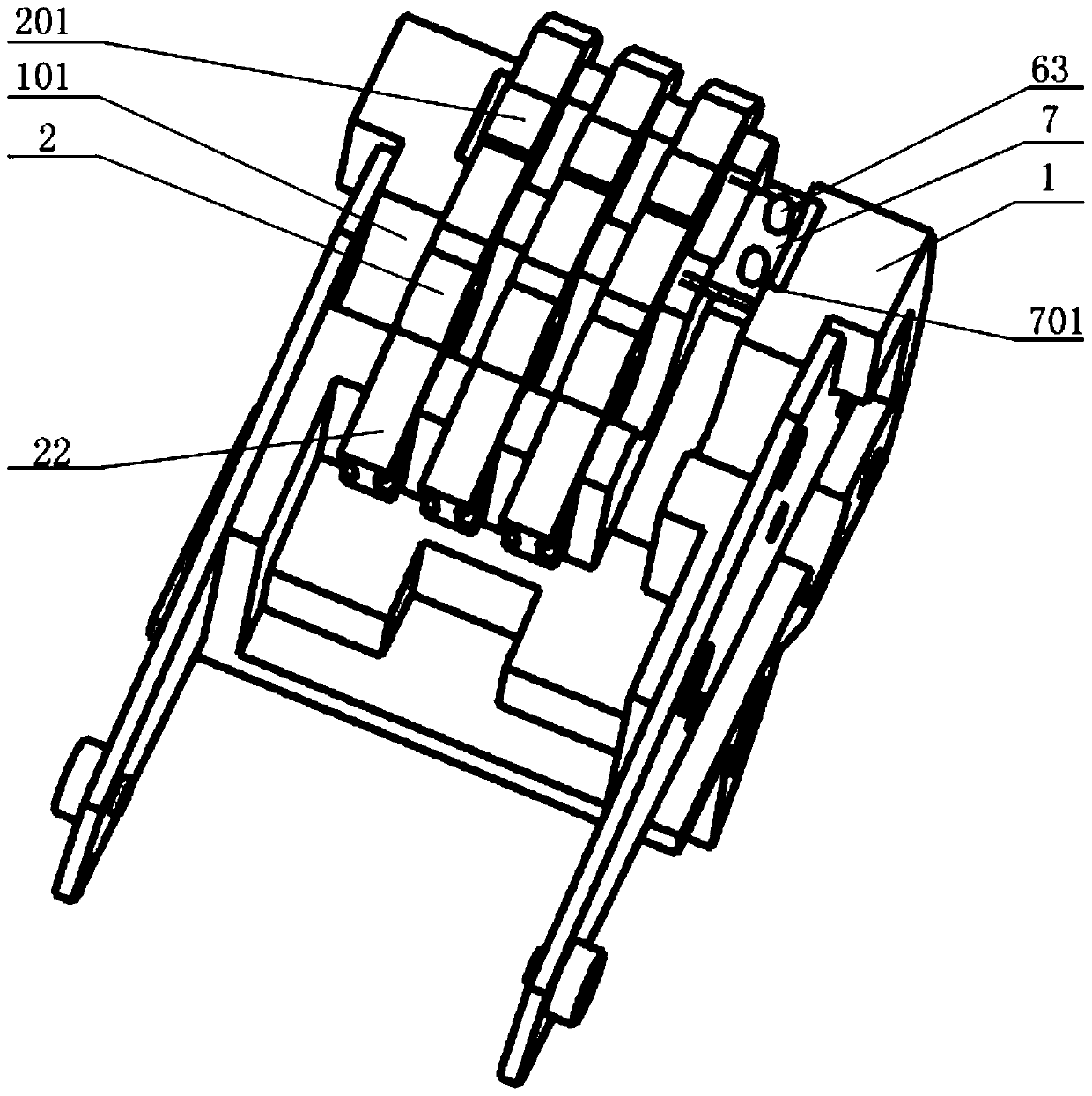
[0022] The following is attached Figures 3 to 5 The given examples further illustrate the specific implementation of the contact mechanism of the circuit breaker of the present invention. The contact mechanism of the circuit breaker of the present invention is not limited to the description of the following embodiments.

[0023] The universal circuit breaker of the present invention connects the circuit by rotating the contact support 1 so that the movable contact on the contact support 1 contacts the static contact.

[0024] Such as image 3 As shown, the middle part of the contact support 1 is provided with a contact piece installation cavity 101, and a plurality of contact pieces 2 are arranged side by side in the contact piece installation cavity 101, and a contact piece 2 is provided between two adjacent contact pieces 2. The insulating partition, the contact sheet 2 and the insulating partition are connected in series through the rotating shaft, the two ends of the ro...


PUM


Abstract

A contact mechanism of a universal circuit breaker, including a contact support, a contact piece pivotally mounted on the contact support and a contact spring, a plurality of contact pieces arranged side by side on the contact support, and a plurality of Guide rods, each contact spring is set on one end of each guide rod, at least one guide rod corresponds to a contact piece, the contact support is provided with a movable cavity for accommodating the contact spring and one end of the guide rod, The guide rod compresses the contact spring to move in the movable cavity, and the other end of the guide rod is provided with a contact end that is in contact with the contact piece; the movable cavity is provided with a first limiter for limiting one end of the contact spring. At the position end, the guide rod is provided with a second limit end that limits the other end of the contact spring. The contact piece rotates to touch the contact end of the guide rod, and the guide rod provides contact for the contact piece by compressing the contact spring. elastic. The invention provides a contact mechanism of a universal circuit breaker with stable performance, simple structure and convenient and fast installation.

Description

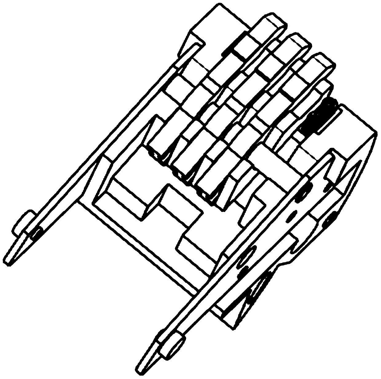
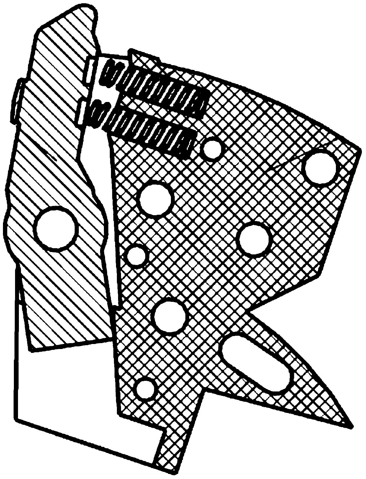
technical field [0001] The invention relates to the field of low-voltage electrical appliances, in particular to a universal circuit breaker, in particular to a contact mechanism of the universal circuit breaker. Background technique [0002] Such as figure 1 , as shown in 2, the current contact mechanism of the universal circuit breaker is to set a spring installation hole for installing the contact spring on the contact support, one end of the contact spring is installed in the spring installation hole and fixed, and the other end protrudes The spring mounting hole provides elastic force for the moving contact piece. [0003] When the contact structure of the universal circuit breaker is used or tested, the moving contact piece is rotating, and the force on the contact spring is not completely acting in the direction of spring compression, and the oblique pressure will cause the spring to be stressed. Bending deformation will eventually cause the force of the spring to n...

Claims


Application Information

Patent Timeline
Patent Type & Authority Patents(China)
IPC IPC(8): H01H73/04
CPCH01H73/04
Inventor 柳德金冯璟刘文娟陈正馨赵鹏
Owner ZHEJIANG CHINT ELECTRIC CO LTD
Learn More