
Drying oven and heat flow circulation control method

A drying box and box technology, which is applied in the direction of drying solid materials, drying chamber/container, drying gas arrangement, etc., can solve problems such as difficulty in removing water vapor in the cavity, temperature field difference that does not meet the requirements of the national standard, and slow heat flow circulation speed, etc. , to achieve the effect of simple, compact and ingenious structure, avoiding air residue and good heating effect

Pending Publication Date: 2019-12-10
HUNAN SUNDY SCI & TECH DEV
View PDF9 Cites 2 Cited by
  • Summary
  • Abstract
  • Description
  • Claims
  • Application Information

AI Technical Summary

Problems solved by technology

[0003] The traditional laboratory drying device mainly uses an electric heating constant temperature blast drying oven, and the electric heating constant temperature blast drying oven needs to manually weigh samples and record data each time.
At the same time, the traditional drying oven has a large volume and consumes a lot of nitrogen when the sample is dried with nitrogen.
At the same time, due to the uneven circulation of air flow in the traditional drying oven, the temperature field difference in the cavity does not meet the requirements of the national standard. At the same time, the heat flow circulation speed of the traditional drying oven is slow, resulting in a slow gas exchange rate, and it is difficult to remove water vapor in the cavity. The drying efficiency lower
At the same time, the air outlet of the heating and blowing component of the traditional drying oven is smaller than the size of the cavity, resulting in a dead angle of ventilation in the cavity, resulting in residual oxygen in the cavity during nitrogen drying, which does not meet the national standard requirements

Method used


Image

  • Drying oven and heat flow circulation control method
  • Drying oven and heat flow circulation control method
  • Drying oven and heat flow circulation control method

Examples


Embodiment Construction

[0041] The present invention will be further described below in conjunction with the accompanying drawings and specific embodiments.

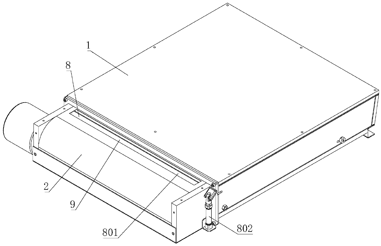
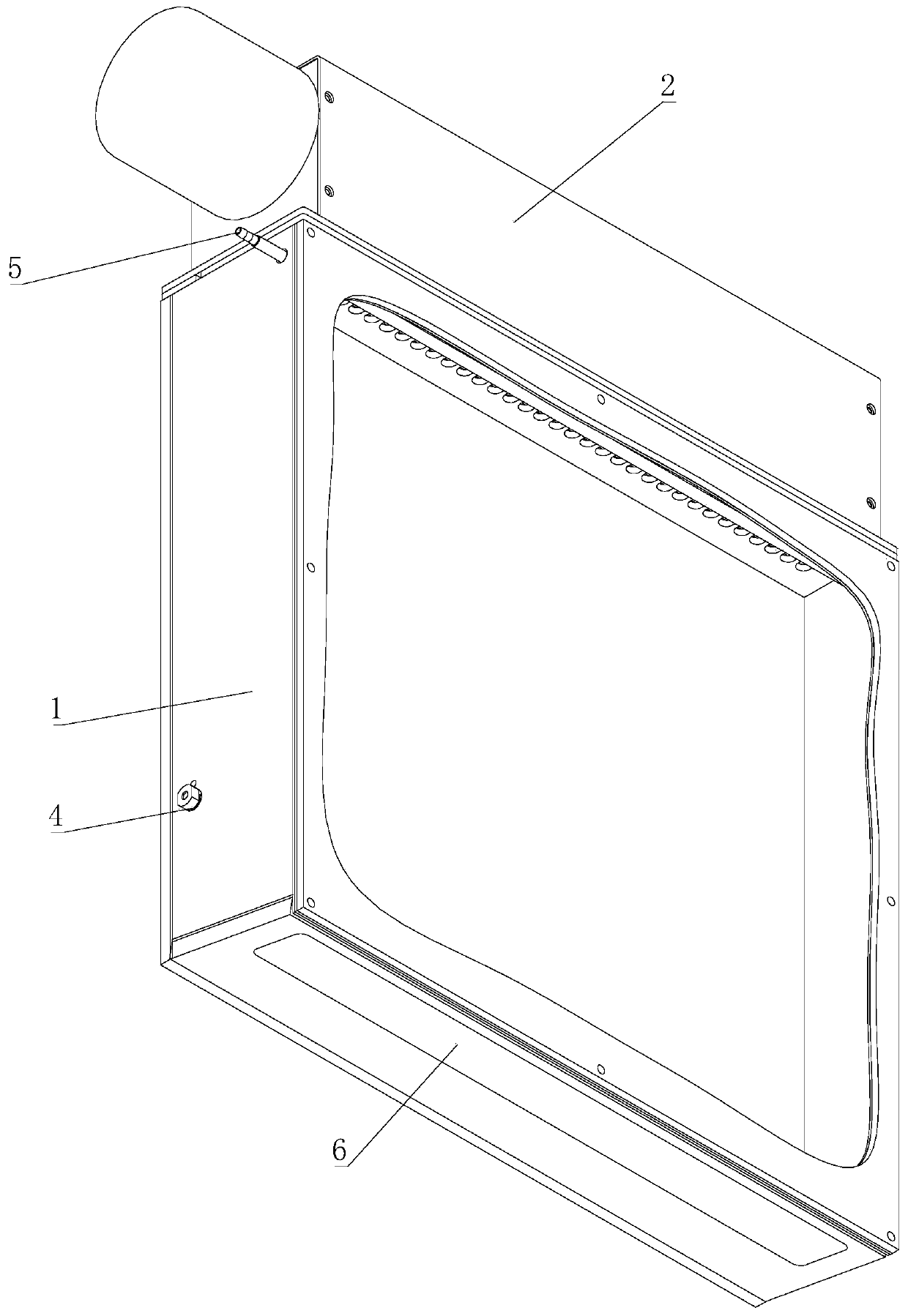
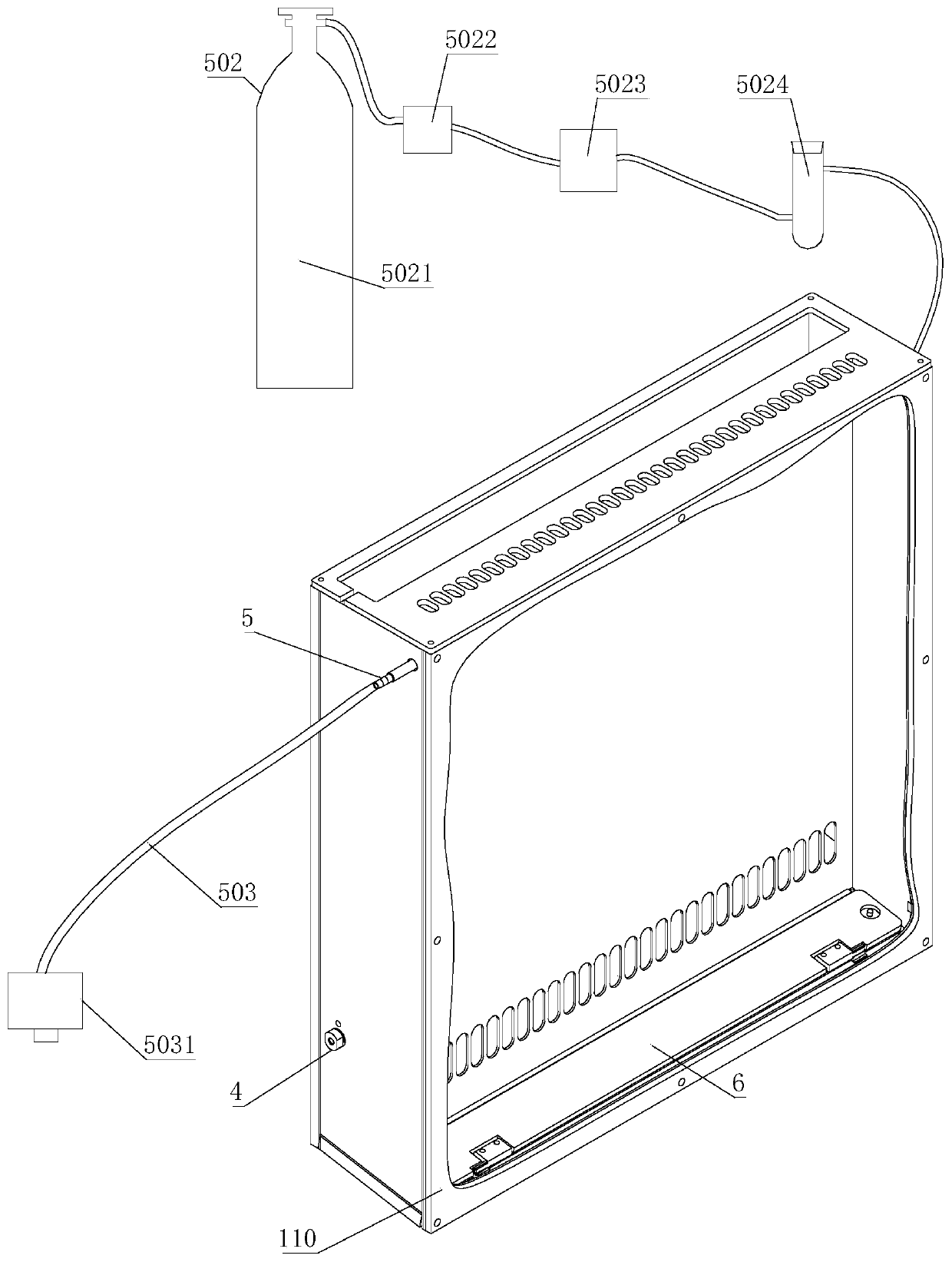
[0042] like Figure 1 to Figure 9 As shown, the drying box of this embodiment is used for drying operations in the moisture determination of samples (such as coal samples), and includes a box body 1 and a chamber formed by the box body 1. A partition 101 is arranged in the chamber for use in Because the chamber is divided into a first chamber 112 and a second chamber 113 arranged up and down; the first chamber 112 is used to dry the sample (that is, a drying chamber for placing a sample tray of a corresponding particle size sample), One end of the first chamber 112 is provided with a sampling door 6, and one end of the casing 1 opposite to the sampling door 6 is provided with a heating chamber 2, and the heating chamber 2 communicates with the first chamber 112 and the second chamber 113 respectively, specifically Specifically, the first chamb...


PUM


Abstract

The invention discloses a drying oven and a heat flow circulation control method, and belongs to the technical field of sample total moisture determination. The problem of low drying efficiency of a current drying oven is solved. According to the technical scheme, the drying oven comprises an oven body and a chamber formed by the oven body in an enclosing mode, and the chamber is internally provided with a separating plate used for dividing the chamber into a first chamber and a second chamber which are arranged up and down; one end of the first chamber is provided with a sample feeding door,and the end, relative to the sample feeding door, of the oven body is provided with a heating cavity; an exhaust port is formed at the position, close to the second chamber, on the heating cavity, andthe heating cavity is provided with a switching door switched between a first position and a second position is arranged at the position of the exhaust port; when the switching door is located at thesecond position, the communication position between the heating cavity and the second chamber is blocked by the switching door, and the exhaust port is opened for performing an outer circulation mode. According to the above technical scheme, the drying oven has the advantages of high drying efficiency and applicability and the like.

Description

technical field [0001] The invention mainly relates to the technical field of sample drying, in particular to a drying oven and a heat flow cycle control method. Background technique [0002] 对于煤样而言,主要是由有机物和无机物组成,而对于煤种无机物水分而言,在各个环节是最容易发生变化的组成部分。 而对于电厂煤场而言,煤中的水分含量是评价煤炭经济和使用价值最基本的指标,煤中水分含量高低直接影响煤中其它组分含量高低或发热量高低,同时对煤的计量、验收、管理也会产生相关联的影响。 Therefore, the determination of the moisture content in coal is an extremely critical link, and the drying oven for the determination of the moisture content of coal samples is also an extremely important component. [0003] 传统的实验室干燥装置主要是采用电热恒温鼓风干燥箱,而电热恒温鼓风干燥箱每次需要人工手动称样和记录数据,自动化程度低,需要有人值守,效率不高。同时传统的干燥箱体积较大,在样品通氮干燥的情况下对氮气消耗量大。同时,传统的干燥箱由于循环气流不均匀,导致腔体内的温场差不满足国标要求,同时传统的干燥箱热流循环速度慢,导致气体交换速度较慢,腔体内水蒸气难以排除,干燥效率较低。同时,传统的干燥箱加热鼓风组件出风口小于腔体大小,导致腔体内存在换气死角,导致腔体内通氮干燥时存在残留的氧气而不满足国标要求。 Contents of the invention [0004] 本发明要解决的技术问题就在于:针对现有技术存在的技术问题,本发明提供一种结构简单、干燥效率高的干燥箱及热流循环控制方法。 [0005] 为解决上述技术问题,本发明提出的技术方案为: [0006] 一种干燥箱,包括箱体以及由箱体围合形成的腔室,所述腔室内设有隔板,用于将腔室分...

Claims


Application Information

Patent Timeline
Patent Type & Authority Applications(China)
IPC IPC(8): F26B9/06F26B21/00F26B21/04F26B25/00F26B25/12F26B25/16
CPCF26B9/06F26B21/001F26B21/004F26B21/04F26B25/00F26B25/16F26B25/12
Inventor 喻季红龚伟业
Owner HUNAN SUNDY SCI & TECH DEV
Learn More