Built-in multi-piece type wet brake

A wet brake, multi-plate technology, used in mechanical drive clutches, clutches, couplings, etc., can solve the problem of uneven distribution of the compression force of the coil spring, larger axial size of the brake housing, and unstable brake braking. and other problems to achieve the effect of avoiding excessive friction temperature, strong braking and recovery effect, and short return time

Active Publication Date: 2019-12-10
襄阳彼勒液压机械有限公司
View PDF11 Cites 0 Cited by
  • Summary
  • Abstract
  • Description
  • Claims
  • Application Information

AI Technical Summary

Problems solved by technology

The arrangement of the helical spring will easily lead to an increase in the axial dimension of the brake housing, which will lead to an increase in the size of the brake and a complex structure. When the helical spring is released, the piston will be pushed back to its original position, which will take a long time to return and the separation of the friction plate will not be complete.
The uneven distribution of the compression force of the coil spring will also cause the brake to be unstable and affect the braking performance
Therefore, we design a joint action of dynamic and static friction plates by squeezing the friction discs through elastic diaphragms. Separation by diaphragm springs can ensure fast and thorough separation of inner and outer friction plates, thereby improving braking reliability. However, due to the elastic film The elasticity of the plate itself is too large, and a slight bending will generate a large amount of elastic recovery force, squeezing the friction plate, which can easily lead to sudden death of the wheel, which not only greatly increases the damage speed of the friction plate, but also may cause the car body to shift due to the tire locking have an accident

Method used


Image

  • Built-in multi-piece type wet brake
  • Built-in multi-piece type wet brake
  • Built-in multi-piece type wet brake

Examples


Embodiment Construction

[0023] The following will clearly and completely describe the technical solutions in the embodiments of the present invention with reference to the accompanying drawings in the embodiments of the present invention. Obviously, the described embodiments are only some, not all, embodiments of the present invention.

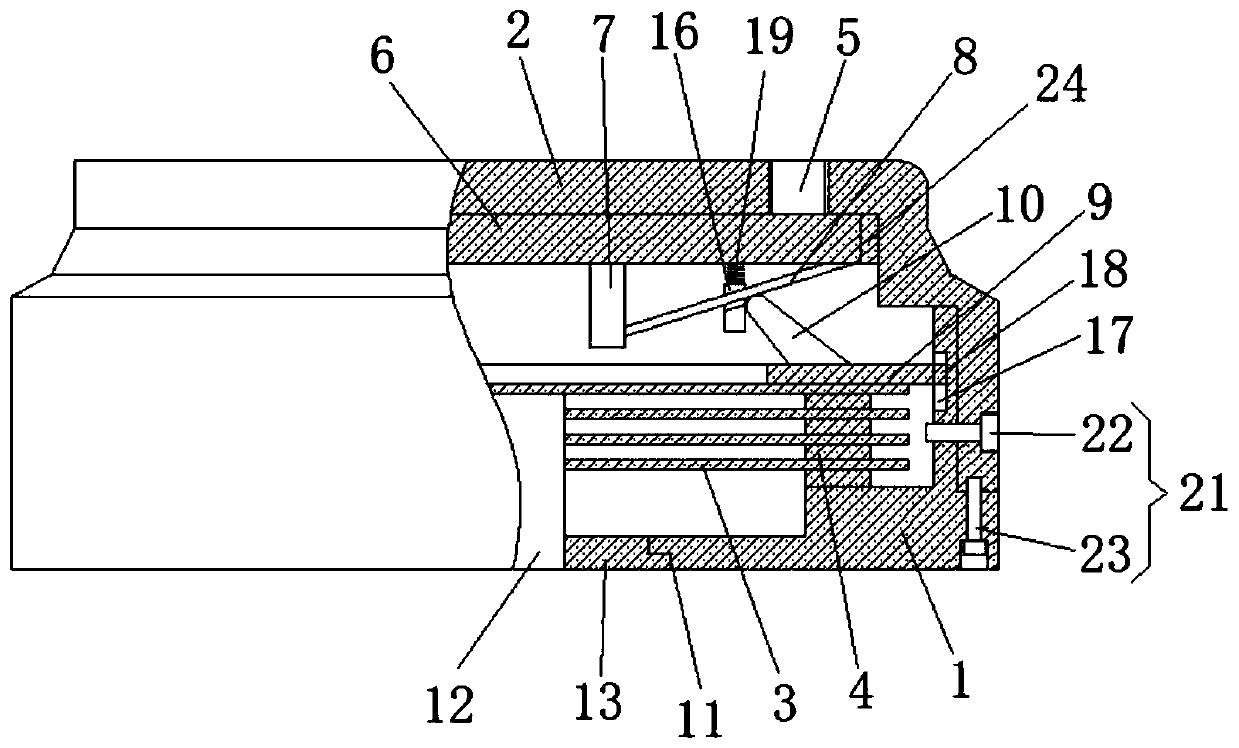
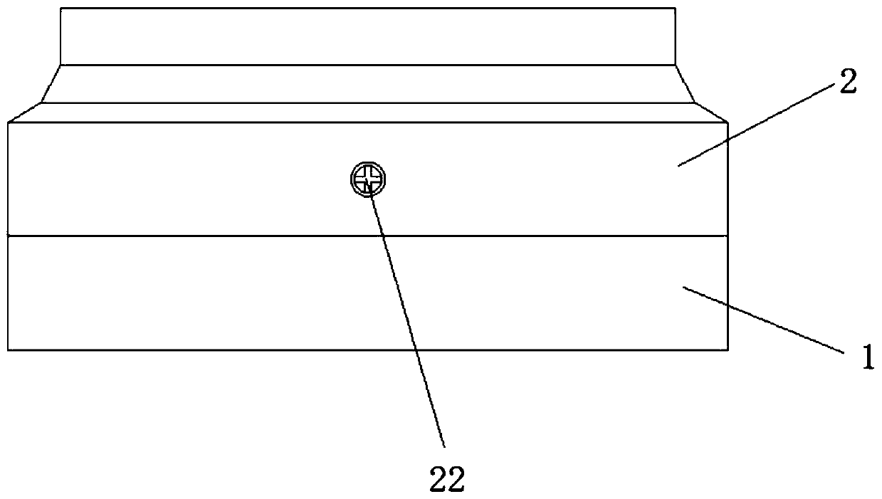
[0024] refer to Figure 1-4 , a built-in multi-plate wet brake, including a housing 1 and a sealing plate 2, the housing 1 and the sealing plate 2 are fixedly connected by bolts 21, the bolts 21 include oil drain bolts 22 and countersunk bolts 23, the oil drain bolts 22 runs through the sealing plate 2 and the housing 1 in turn horizontally, and the countersunk head bolt 23 vertically penetrates the housing 1 and is fixedly connected with the sealing plate 2. By setting the oil drain bolt 22, it is more convenient and quick to replace the friction oil without disassembling it completely The addition and discharge of friction oil can be realized, which reduces labor i...


PUM


Abstract

The present invention relates to the technical field of brakes, in particular to a built-in multi-piece type wet brake. The built-in multi-piece type wet brake includes a shell and a sealing plate, the shell and the sealing plate are fixedly connected through bolts, multiple dynamic friction plates and multiple static friction plates are arranged inside the shell and are stacked in the shell at intervals, the top end of the sealing plate is provided with a brake push rod, the brake push rod penetrates the top end of the sealing plate, and a seal plate is fixedly welded to the bottom end of thebrake push rod. The internal structure of the brake can be simplified by arranging an elastic diaphragm, and the elastic diaphragm is arranged so that the return time of the friction plates can be shorter and separation can be more thorough; and in addition, a buffer structure is designed, so that the contact pressure of the friction plates is gradually increased, a previous direct increase braking manner is changed, the occurrence of tire lockup is prevented, the safety of the brake is improved, the damage to the friction plates is greatly reduced, the structure is simple, the braking effectis better, and the built-in multi-piece type wet brake is suitable for promotion.

Description

technical field [0001] The invention relates to the technical field of brakes, in particular to a built-in multi-plate wet brake. Background technique [0002] Automobile brakes are one of the most important components of automobiles, and their braking performance directly affects the safety of automobiles. Brakes are used to slow down the automobile or stop the automobile within the shortest distance according to demand. They are mainly divided into drum type and disc type. . Although the drum brake vehicle is low in cost and dustproof, it is large in size and heavy in weight, and is not easy to dissipate heat. Disc brakes have good heat dissipation, good braking stability, and small size and weight. Among the disc brakes, the multi-disc wet brake is a disc brake whose friction plates work in an oil-immersed closed environment. It has the advantages of large braking torque, long service life, strong anti-fading and anti-pollution capabilities, and maintenance-free. Theref...

Claims


Application Information

Patent Timeline
Patent Type & Authority Applications(China)
IPC IPC(8): F16D13/54F16D13/70F16D13/72
CPCF16D13/54F16D13/70F16D13/72F16D2300/22F16D2300/26
Inventor 张金生
Owner 襄阳彼勒液压机械有限公司
Why Eureka
Try Eureka