A manufacturing process of a double-layer special-shaped flat pot
A production process and special-shaped technology, which is applied in the production process of double-layer special-shaped flat pots, can solve problems such as low yield and easy leakage, and achieve the effects of increasing yield, improving accuracy, and reducing operation difficulty
- Summary
- Abstract
- Description
- Claims
- Application Information
AI Technical Summary
Problems solved by technology
Method used
Image

Examples
Embodiment 1
[0047] A manufacturing process of a double-layer special-shaped flat pot, comprising the following steps:
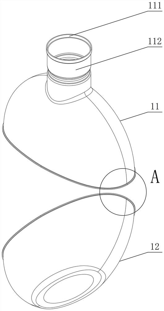
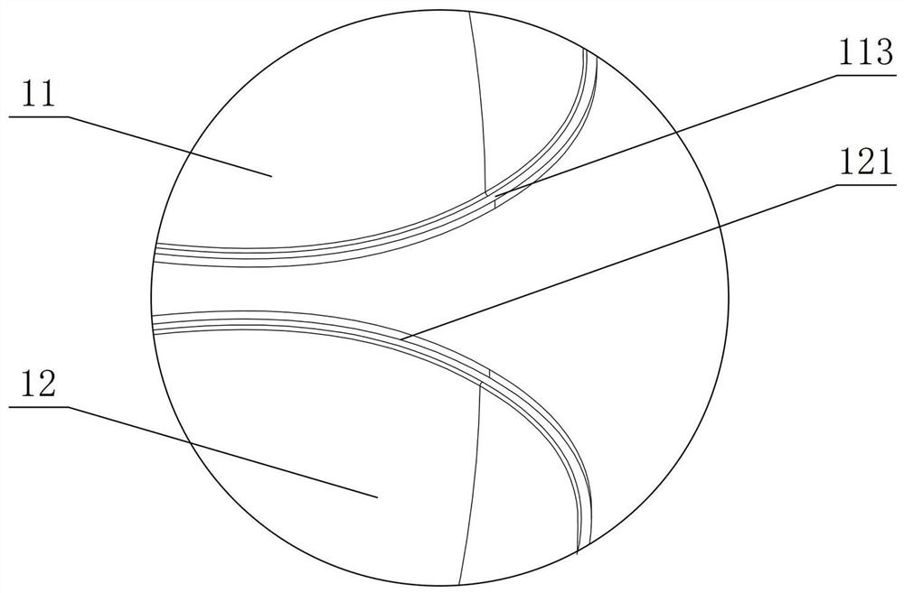
[0048] (a) Take an upper liner 11, the upper part of the upper liner 11 is provided with an inner liner mouth 112, and the bottom of the upper liner 11 is provided with an upper convex edge 113, take the inner liner 12, and the lower liner 12 top is provided with lower flange 121, the width of described upper flange 113, described lower flange 121 is 1.0mm, and described upper flange 113 cooperates with described lower flange 121 to form welding edge 13, described The top of the mouth 112 of the inner tank is provided with a mouth welding flange 111;
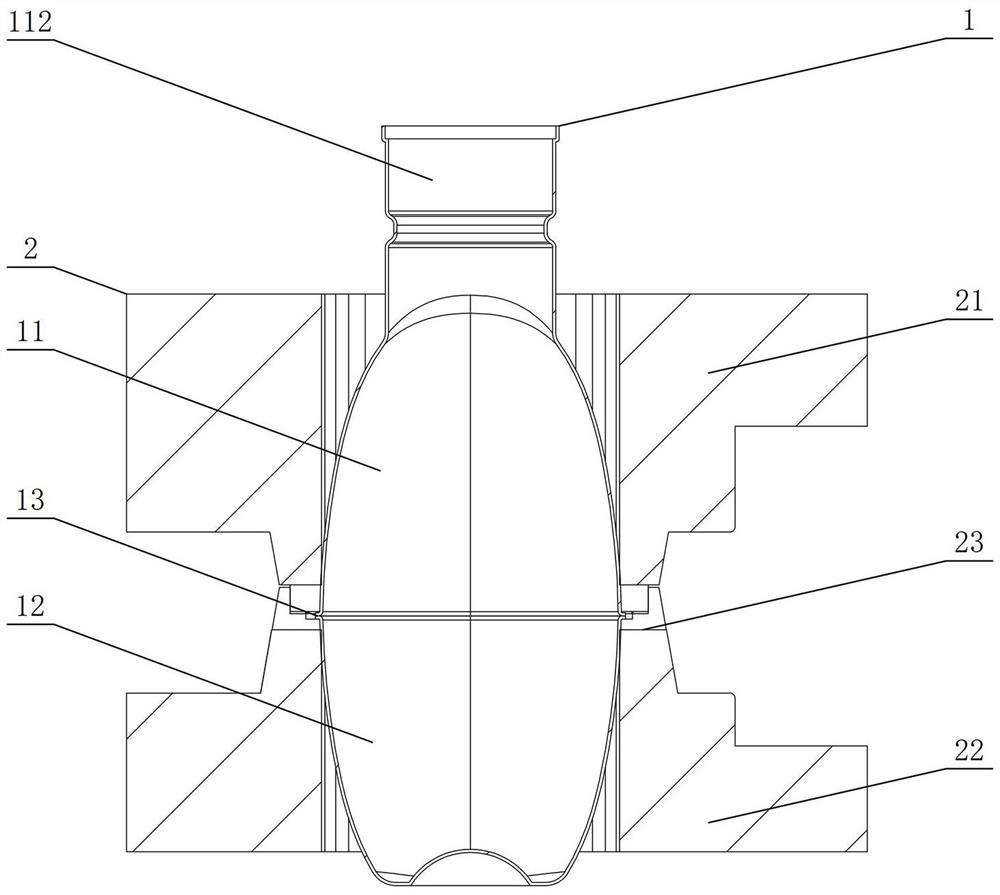
[0049] (b) Take a liner spot welding fixture 2, place the upper liner 11 and the lower liner 12 in the liner spot welding fixture 2 for positioning, and perform spot welding on the welding edge 13 Preliminarily fix the upper inner container 11 and the lower inner container 12, take out the upper inner container 11 and the...
Embodiment 2
[0073] In the step (a), take an upper liner 11, the upper part of the upper liner 11 is provided with an inner liner mouth 112, and the bottom of the upper liner 11 is provided with an upper convex edge 113, take the inner liner 12, The top of the lower liner 12 is provided with a lower flange 121, the width of the upper flange 113 and the lower flange 121 is 1.5 mm, and the upper flange 113 cooperates with the lower flange 121 to form a welding Edge 13, the top of the mouth 112 of the liner is provided with a mouth welding flange 111;
[0074] In the step (f), push the mouth 112 of the liner to move toward the inside of the outer casing 3 until the distance between the outer edge 111 of the welding flange of the mouth and the outer edge of the mouth 33 of the outer shell is equal to the length Stop at D, the length D is 1.5mm.
[0075] Other implementations are the same as in Example 1.
Embodiment 3
[0077] In the step (a), take an upper liner 11, the upper part of the upper liner 11 is provided with an inner liner mouth 112, and the bottom of the upper liner 11 is provided with an upper convex edge 113, take the inner liner 12, The top of the lower liner 12 is provided with a lower flange 121, the width of the upper flange 113 and the lower flange 121 is 1.2mm, and the upper flange 113 cooperates with the lower flange 121 to form a welding Edge 13, the top of the mouth 112 of the liner is provided with a mouth welding flange 111;
[0078] In the step (f), push the mouth 112 of the liner to move toward the inside of the outer casing 3 until the distance between the outer edge of the welding flange 111 of the mouth and the outer edge of the mouth 33 of the outer shell is the length Stop at D, the length D is 1.2mm;
[0079] Other implementations are the same as in Example 1.
PUM
| Property | Measurement | Unit |
|---|---|---|
| width | aaaaa | aaaaa |
| length | aaaaa | aaaaa |
| width | aaaaa | aaaaa |
Abstract
Description
Claims
Application Information
 - R&D
- Intellectual Property
- Life Sciences
- Materials
- Tech Scout
- Unparalleled Data Quality
- Higher Quality Content
- 60% Fewer Hallucinations
Browse by: Latest US Patents, China's latest patents, Technical Efficacy Thesaurus, Application Domain, Technology Topic, Popular Technical Reports.
© 2025 PatSnap. All rights reserved.Legal|Privacy policy|Modern Slavery Act Transparency Statement|Sitemap|About US| Contact US: help@patsnap.com