
Automatic laminating machine for optical filter

A laminating machine, automatic technology, applied in optics, optical components, installation and other directions, can solve the problems of low lamination accuracy, high labor cost, high labor intensity, etc., to achieve no health hazards, high lamination accuracy, artificial low cost effect

Pending Publication Date: 2019-12-10
厦门贝莱信息科技有限公司
View PDF0 Cites 3 Cited by
  • Summary
  • Abstract
  • Description
  • Claims
  • Application Information

AI Technical Summary

Problems solved by technology

[0004] In order to solve the problems of low manual operation efficiency, high labor intensity, high labor cost, poor glue dispensing effect, low lamination accuracy and low yield rate, frequent rework required, large glue waste, small product volume and easy to damage the product, The waste of products is high, the cost of materials is high, the eyes are prone to fatigue when working under a microscope, the damage to the eyes is large, and there are major health risks. The present invention adopts the following technical solutions:

Method used


Image

  • Automatic laminating machine for optical filter

Examples


Embodiment Construction

[0015] Preferred embodiments of the present invention will be described in detail below in conjunction with the accompanying drawings.

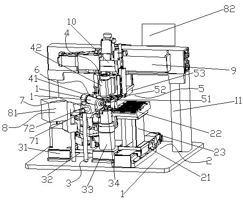
[0016] see figure 1 , an automatic bonding machine for filter wave plates, including a base 1, a feeding mechanism 2, a rotating mechanism 3, a suction nozzle feeding mechanism 4, a correction mechanism 5, an automatic dispensing mechanism 6, a UV curing mechanism 7, and a CCD vision mechanism 8 , X-axis linear module 9 and Z-axis linear module 10, the jig rotation mechanism 3 is located in the center of the base, the feeding mechanism 2, the correction mechanism 5, the automatic dispensing mechanism 6, the UV curing mechanism 7, The CCD visual mechanism 8 is distributed and arranged on the outside of the rotating mechanism 3 in the counterclockwise direction and is spaced from each other at a certain distance without interference. The X-axis linear module 9 is arranged on one side of the base 1 through the mounting frame 11. The Z-axis line...


PUM


Abstract

The invention discloses an automatic laminating machine for an optical filter. The machine comprises a base, a feeding mechanism, a rotating mechanism, a suction nozzle material taking mechanism, a correcting mechanism, an automatic dispensing mechanism, a UV curing mechanism, a CCD visual mechanism, an X-axis linear module and a Z-axis linear module. A jig rotating mechanism is arranged in the center of the base, and the feeding mechanism, the correcting mechanism, the automatic dispensing mechanism, the UV curing mechanism and the CCD visual mechanism are arranged on the outer side of the rotating mechanism. The X-axis linear module is arranged on the upper portion of one side of the base, the Z-axis linear module is movably arranged on the X-axis linear module, and the suction nozzle material taking mechanism is arranged on the Z-axis linear module and located above the rotating mechanism. Products are automatically clamped and fixed to a clamping jaw, corrected and subjected to rotary dispensing and curing in sequence, manual operation is not needed, the operation efficiency is high, the labor intensity is low, the labor cost is low, the dispensing effect is good, the fitting precision is high, the yield is high, frequent reworking is not needed, the products are not easily damaged, glue solution product waste is small, the material cost is low, no harm is caused to eyes, and hidden health hazards are avoided.

Description

technical field [0001] The invention belongs to the field of automatic equipment, and in particular relates to an automatic bonding equipment for optical filter wave plates and collimators. Background technique [0002] The filter wave plate can be used only after being fixedly bonded with the collimator. The two are fixed and bonded together by dispensing glue. Working under a microscope, at present, the lamination and dispensing of the filter wave plate is done manually under the microscope. This manual operation method can meet certain production needs, but there are also major defects. Low operating efficiency, high labor intensity, high labor cost, poor dispensing effect, low lamination accuracy, low yield rate, frequent rework, large glue waste, small product volume, easy to bruise the product, large product waste, high material cost, microscope Eyes are prone to fatigue when working under the sun, which will cause great damage to the eyes and pose a major health risk...

Claims


Application Information

Patent Timeline
Patent Type & Authority Applications(China)
IPC IPC(8): B05C13/02B05C5/02B05D3/06G02B7/00
CPCB05C13/02B05C5/0208B05D3/067G02B7/006G02B7/00
Inventor 叶孝东吴宏毅张灼广
Owner 厦门贝莱信息科技有限公司
Learn More