Switching converter and control circuit and method thereof

A switching converter and control circuit technology, applied in control/regulation systems, DC power input conversion to DC power output, instruments, etc., can solve the problem of large compensation amount of ripple compensation module, deviation of output voltage, and deterioration of dynamic characteristics And other issues

Pending Publication Date: 2019-12-06
HANGZHOU SILAN MICROELECTRONICS
View PDF0 Cites 15 Cited by
  • Summary
  • Abstract
  • Description
  • Claims
  • Application Information

AI Technical Summary

Problems solved by technology

[0005] However, the ripple compensation module located outside the chip needs to add additional components, and the ripple compensation module located inside the chip may introduce DC offset and cause the output voltage to deviate
Moreover, in order to meet the system stability requirements under different input and output voltages, the compensation amount of the ripple compensation module of the switching converter is designed to be large, resulting in poor dynamic characteristics

Method used


Image

  • Switching converter and control circuit and method thereof
  • Switching converter and control circuit and method thereof
  • Switching converter and control circuit and method thereof

Examples


Embodiment Construction

[0112] Various embodiments of the invention will be described in more detail below with reference to the accompanying drawings. In the various drawings, the same elements are denoted by the same or similar reference numerals. For the sake of clarity, various parts in the drawings have not been drawn to scale.

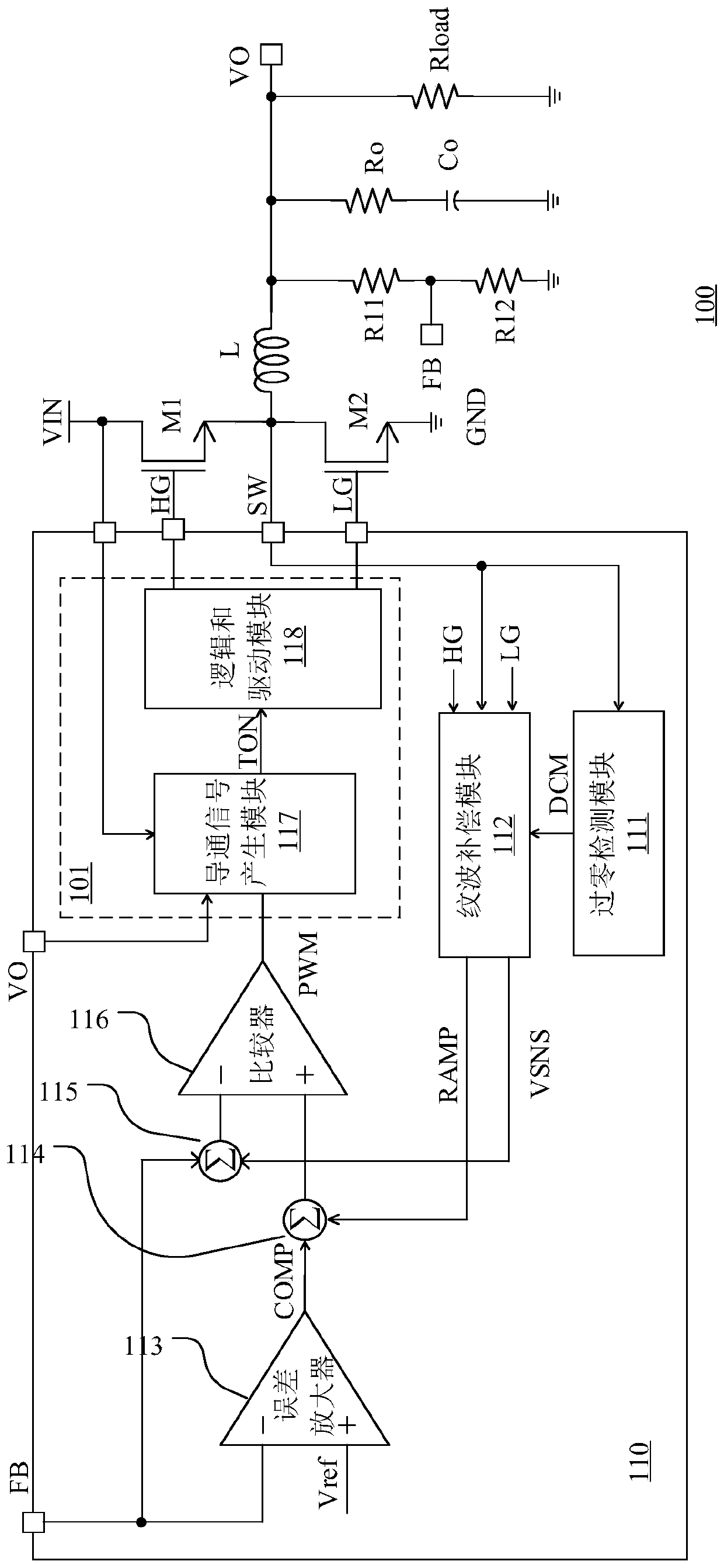
[0113] figure 1 A schematic block diagram of a switching converter according to an embodiment of the present invention is shown. like figure 1 As shown, the switching converter 100 is, for example, a BUCK topology, including a main circuit and a control circuit 110 .

[0114] The main circuit includes switches M1 and M2 connected in series between the input terminal VIN and the ground terminal GND, an inductor L connected between the middle node SW of the switches M1 and M2 and the output terminal VO, and an inductor L connected in series at the output terminal VO The sampling resistors R11 and R12 between the ground terminal GND and the output capacitor Co connecte...


PUM


Abstract

The invention discloses a switching converter and a control circuit and control method thereof. The control circuit comprises a ripple compensation module. According to a switching node voltage between a first switching tube and a second switching tube, a first driving signal of the first switching tube and a second driving signal of the second switching tube, the ripple compensation module generates a slope compensation signal and a direct current compensation signal, wherein the direct current compensation signal is a sampling signal of the slope compensation signal; a control circuit adoptsthe slope compensation signal to improve transient characteristics, and the direct current compensation signal is adopted to eliminate imbalance introduced by the ripple compensation module.

Description

technical field [0001] The present invention relates to the field of switching power supplies, and more particularly, to a switching converter based on a constant on-time control mode, a control circuit and a control method thereof. Background technique [0002] With the advancement of circuit electronics technology, switching power supplies continue to develop in the direction of high power density, high efficiency, and high reliability. In switching power supplies of various electronic products, switching converters are widely used. Switching converters can adopt various topologies, such as BOOST, BUCK, BOOST-BUCK, and flyback topologies. During operation, the switching converter, for example, uses PWM modulation (Pulse Width Modulation, pulse width modulation) to control the conduction state of the switch tube, thereby controlling the power transmission from the input end to the output end, so as to provide a stable output voltage and / or current . [0003] When using t...

Claims


Application Information

Patent Timeline
IPC IPC(8): H02M3/158H02M1/14
CPCH02M3/158H02M1/143
Inventor 王军陈华捷宁志华余永强
Owner HANGZHOU SILAN MICROELECTRONICS
Why Eureka
Try Eureka