
Acoustic emission source positioning method and system based on a random sensor network

A sensor network and acoustic emission source technology, which is applied in the direction of material analysis, positioning, and radio wave measurement system using acoustic emission technology, can solve problems such as the influence of acoustic emission source positioning results, achieve high positioning accuracy and stability, avoid No solution and multiple solutions, the effect of ensuring accuracy

Active Publication Date: 2019-12-06
CENT SOUTH UNIV
View PDF4 Cites 2 Cited by
  • Summary
  • Abstract
  • Description
  • Claims
  • Application Information

AI Technical Summary

Problems solved by technology

Patent CN102435980A discloses an acoustic emission source or microseismic source positioning method based on analytical solution, which has high calculation efficiency, but this method is only applicable to the acoustic emission source positioning problem of fixed geometry, and the sensor needs to be placed at a specific position
CN102590790A discloses a non-iterative positioning algorithm for jointly solving velocity and target position, which can be used for acoustic emission target positioning under the condition of unknown propagation velocity, and can comprehensively utilize all sensors, but this method needs to pre-calculate the unary cubic Solve the equation, the wave velocity has no solution or multiple solutions will have a serious impact on the results of acoustic emission source location

Method used


Image

  • Acoustic emission source positioning method and system based on a random sensor network
  • Acoustic emission source positioning method and system based on a random sensor network
  • Acoustic emission source positioning method and system based on a random sensor network

Examples


Embodiment 1

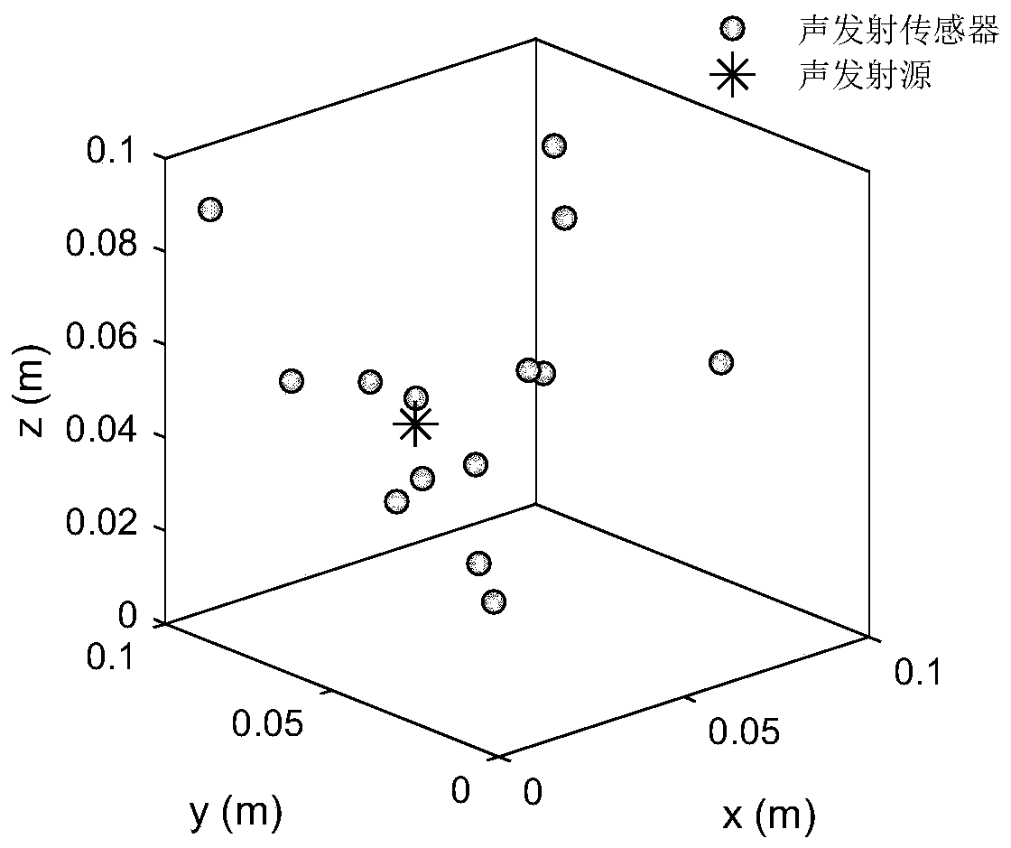
[0059] This embodiment discloses a method for locating an acoustic emission source based on a random sensor network, which includes the following steps:

[0060] Arrange a random sensor network in the monitoring system (near the acoustic emission source to be measured), that is, place n acoustic emission sensors that are not all coplanar at any position in the monitoring system, and the coordinates of the n acoustic emission sensors are (x i ,y i ,z i )(i=1,2,...,n);

[0061] Use n acoustic emission sensors to perceive the acoustic emission signal of the acoustic emission source, record the time when each acoustic emission sensor receives the acoustic emission signal, and set the time when the i-th acoustic emission sensor receives the acoustic emission signal as t i (i=1,2,...,n).

[0062] The coordinates x, y, z of the acoustic emission source are obtained by the following formula:

[0063]

[0064] in,

[0065]

[0066]

[0067]

[0068] as well as

Embodiment 2

[0070] This embodiment discloses an acoustic emission source localization system based on a random sensor network, including a data processing module; the data processing module adopts the positioning method described in Embodiment 1, based on the coordinates of each acoustic emission sensor in the random sensor network and their The coordinates (x, y, z) of the acoustic emission source are calculated at the time of receiving the acoustic emission signal to realize the positioning of the acoustic emission source.


PUM


Abstract

The invention discloses an acoustic emission source positioning method and system based on a random sensor network. The system is characterized in that the random sensor network comprises n acoustic emission sensors which are not totally arranged in a coplanar manner at any position in a monitoring system, wherein n is more than or equal to 6; the coordinates of the n acoustic emission sensors arerecorded as (xi, yi, zi), and i is 1, 2, and n; the time of the n acoustic emission sensors receiving the acoustic emission signals are recorded as t1, t2, and tn; and the acoustic emission source coordinates (x, y, z) are calculated according to a given localization formula. The method and the system can realize high positioning precision and stability.

Description

technical field [0001] The invention relates to a method and system for localizing an acoustic emission source based on a random sensor network. Background technique [0002] Acoustic emission positioning technology is widely used in the research of the fracture and instability mechanism of rocks, concrete and other materials. A major and basic step in the analysis and research of acoustic emission is to identify the location of damage and destruction. Therefore, an accurate acoustic emission source location method is crucial. For a long time, in order to improve the accuracy of AE source location, scholars have proposed many location methods. However, most positioning methods need to measure the wave velocity in advance, and the wave velocity measurement error is inevitable. Practical applications show that the measured value of wave velocity is greatly affected by the distance between sensors, and a small change in the distance between sensors can cause a huge change in ...

Claims


Application Information

Patent Timeline
Patent Type & Authority Applications(China)
IPC IPC(8): G01N29/14G01N29/44G01N29/36G01S5/22
CPCG01N29/14G01N29/36G01N29/44G01N29/449G01N2291/0232G01N2291/0289G01S5/22
Inventor 周子龙芮艺超周静蔡鑫程瑞山董陇军
Owner CENT SOUTH UNIV
Learn More