
Underwater sampling device for shallow water area

A sampling device and shallow water area technology, applied in the field of underwater detection, can solve the problem of a single underwater sampling module, etc., and achieve the effect of simple structure, easy maintenance, installation and disassembly

Inactive Publication Date: 2019-12-06
东莞市奇趣机器人科技有限公司
View PDF0 Cites 0 Cited by
  • Summary
  • Abstract
  • Description
  • Claims
  • Application Information

AI Technical Summary

Problems solved by technology

[0002] At present, the samplers used for underwater detection are generally used for the investigation of the marine environment and resources. Both at home and abroad, the sampling environment is positioned at a place with a greater depth and a more complex seabed environment. The requirements for the insulation and pressure of the sample It is also getting higher and higher, because completing such an underwater sampling operation is not only what a single underwater sampling module can complete, but also requires fixed platforms on the water surface (stationary ships, offshore platforms, etc.) The lower carrier is used as supporting equipment; the most commonly used and simple collection method is powered by springs, represented by the "MajorPair" sampler commonly used on Alvin deep submersibles. The design of the collection part is similar to the principle of a syringe. The potential energy in the spring drives the piston in the "needle" to suck the external water into the "needle"; another way to drive the sampling is through a motor, which represents a kind of gas developed by WHOI Jeffrey (Jeffrey) et al. Tight pressure-holding sampler, the motor can stably control the rate of sample collection, and even control the inflow and outflow of samples; the above-mentioned sampler is not suitable for sampling in shallow water areas such as lakes and offshore

Method used


Image

  • Underwater sampling device for shallow water area
  • Underwater sampling device for shallow water area
  • Underwater sampling device for shallow water area

Examples


Embodiment 1

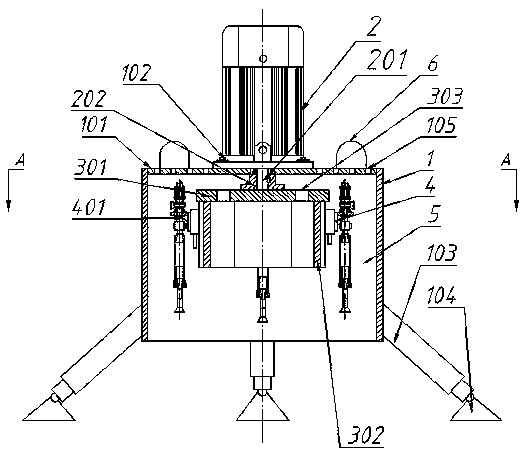
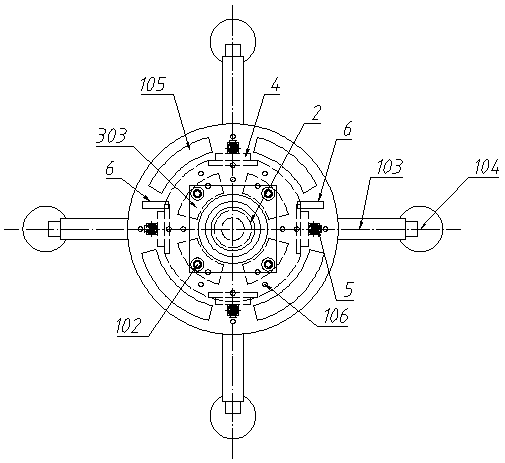
[0040] This embodiment is mainly used for underwater sampling work of lakes, such as Figure 1-3 As shown, an underwater sampling device used in shallow water areas includes an installation cylinder 1, and a rotating motor 2 is installed on the top plate 101 of the installation cylinder 1 through bolts 102, and the output shaft 201 of the rotating motor 2 passes through The top plate 101 is connected to the top cover 301 of the rotating cylinder 3; the bottom of the top cover 301 is provided with four motor mounting plates 302, and each of the motor mounting plates 302 is fixedly equipped with a linear motor 4, and the The linear motor 4 is equipped with a sampler 5 through a bracket 401; on the top plate 101 of the installation cylinder 1, there are also two hydraulic boxes 6 that provide power for the hydraulic telescopic rod 103, and the four hydraulic telescopic rods 103 are fixedly installed Below the outside of the cylinder wall of the installation cylinder 1, the four h...


PUM


Abstract

The invention discloses an underwater sampling device for a shallow water area. The underwater sampling device comprises a mounting barrel; a rotating motor is mounted on a top plate of the mounting barrel through bolts; an output shaft of the rotating motor penetrates through the top plate to be connected to a top cover of a rotating barrel; a plurality of motor mounting plates are arranged at the bottom of the top cover; linear motors are fixedly mounted on the motor mounting plates; samplers are mounted on the linear motors through brackets; hydraulic boxes for providing power for hydraulictelescopic rods are further arranged on the top plate of the mounting barrel; the hydraulic telescopic rods are fixedly mounted below the outer side of the barrel wall of the mounting barrel; and foot cups are mounted on the hydraulic telescopic rods. According to the device, the multiple samplers are arranged, so that multiple sampling in the same region is achieved, the working efficiency is improved, and the data analysis work is facilitated.

Description

technical field [0001] The invention belongs to a sampler in the technical field of underwater detection, and in particular relates to an underwater sampling device used in shallow water areas. Background technique [0002] At present, the samplers used for underwater detection are generally used for the investigation of the marine environment and resources. Both at home and abroad, the sampling environment is positioned at a place with a greater depth and a more complex seabed environment. The requirements for the insulation and pressure of the sample It is also getting higher and higher, because completing such an underwater sampling operation is not only what a single underwater sampling module can complete, but also requires fixed platforms on the water surface (stationary ships, offshore platforms, etc.) The lower carrier is used as supporting equipment; the most commonly used and simple collection method is powered by springs, represented by the "MajorPair" sampler com...

Claims


Application Information

Patent Timeline
IPC IPC(8): G01N1/14G01N1/34
CPCG01N1/14G01N1/34
Inventor 陈海华郑漫胡常华
Owner 东莞市奇趣机器人科技有限公司
Learn More