
Safety blindbrick

A blind road and floor tile technology, applied in the directions of roads, roads, mechanical audible signals, etc., can solve the problem that blind road turns cannot play a good warning and reminder effect, and achieve the effect of good road guidance.

Inactive Publication Date: 2019-12-06
CHINA CONSTR SECOND ENG BUREAU LTD
View PDF6 Cites 6 Cited by
  • Summary
  • Abstract
  • Description
  • Claims
  • Application Information

AI Technical Summary

Problems solved by technology

[0005] The purpose of the present invention is to provide a safe tactile floor tile that can issue an alarm and remind blind people of the turning direction in view of the problem that the above-mentioned tactile turn cannot play a good warning and reminder role.

Method used


Image

  • Safety blindbrick
  • Safety blindbrick
  • Safety blindbrick

Examples


Embodiment 1

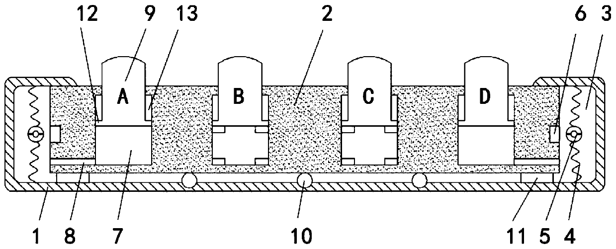
[0021] Such as Figure 1-2 As shown, a safety tactile floor tile includes a shell 1, and a brick body 2 is sealed and slidably connected in the shell 1. It is worth mentioning that a plurality of rolling balls 10 are embedded in the inner bottom of the shell 1, and the brick body 2 and the The ball 10 is rollingly connected, and the bottom surface of the brick body 2 is fixedly connected with two sealing blocks 11. The sealing block 11 is connected to the inner side wall of the housing 1 in a sliding and sealing manner. A vibration chamber 3 is provided between the housing 1 and the brick body 2 to vibrate The side wall of the cavity 3 is fixedly connected with a rattle 5 through a spring 4, and the brick body 2 is embedded with a permanent magnet block 6 at the corresponding position of the rattle 5. The rattle 5 is made of magnetic material, and the rattle 5 and the permanent magnet block 6 Different poles attract each other, and when the brick body 2 slides in the housing 1...

Embodiment 2

[0026] Such as image 3 As shown, the difference between this embodiment and Embodiment 1 is that: the bottom surface of the chute 7 is fixedly connected with a threaded rod 14, the threaded rod 14 is a coarse thread, the thread lead angle is greater than the equivalent friction angle of the screw pair, and does not have an automatic Locking, the upper end of the threaded rod 14 extends into the protruding block 9 and is threadedly connected with the protruding block 9 .

[0027] When the blind person stepped on the raised block 9, the raised block 9 moved in the chute 7, and because the raised block 9 was threaded with the threaded rod 14, the raised block 9 turned to the direction that the road turned, and the blind person could turn according to the raised block 9. The direction of rotation of the block 9 is used to judge the turning direction of the road ahead, which plays a good role in leading the way.


PUM


Abstract

The invention belongs to the field of blind person guiding devices, and particularly relates to a safety blindbrick. The safety blindbrick comprises a shell. A brick body is slidingly connected into the shell in a sealed manner, vibration cavities are formed between the shell and the brick body, rings are fixedly connected to the side walls of the vibration cavities through springs, permanent magnets are embedded into the positions, corresponding to the rings, of the brick body, the rings are made of magnetic materials, the rings and the permanent magnets are in heterospolar attraction, four sliding grooves are formed in the brick body, the sliding grooves communicate with the vibration cavities through vent holes, convex blocks are slidingly connected into the sliding grooves through limiting mechanisms in a sealed manner, and the upper ends of the convex blocks stretch out of the brick body. When the walking route of a blind person deviates from a blind, the brick body slightly slides, alarm sound is sent through the rings, the blind person is reminded of correcting the route, dangerous accidents caused by the fact that the blind person deviates from the blind are avoided, the blind person can judge the turning directions of roads ahead according to the rotating directions of the convex blocks, and a good way guiding effect is achieved.

Description

technical field [0001] The invention belongs to the field of guiding devices for the blind, and in particular relates to floor tiles for safety blind passages. Background technique [0002] Blind pavement is a convenient road facility for blind people to travel safely. Generally, it is paved with three types of bricks, one is strip-shaped guiding bricks to guide blind people to move forward with confidence; the other is reminder bricks with dots to remind blind people that there are obstacles ahead; the other is blind road danger warning guiding bricks, The dots are larger. [0003] Most of the existing tactile floor tiles with round dots are simple in structure and can only play the role of simple guiding and prompting. When a blind person is walking, the route will inevitably have a slight deviation, but the blind person cannot perceive it at this time. This slight deviation will cause a large deviation during the accumulation process of a long road section, so that the ...

Claims


Application Information

Patent Timeline
IPC IPC(8): E01C15/00E01C5/04E01C11/00G08B21/02G08B3/02
CPCE01C5/04E01C11/00E01C15/00G08B3/02G08B21/02
Inventor 徐凯歌
Owner CHINA CONSTR SECOND ENG BUREAU LTD
Learn More