
Telescopic solar panel with angle adjusting function

A solar panel and angle adjustment technology, applied in solar thermal power generation, solar thermal energy, solar thermal collectors, etc., can solve the problems of poor telescopic effect, inability to change the wind-receiving area, and a lot of dust from solar panels, and achieve the overall range The effect of reducing, reducing the wind-receiving area and reducing the frequency of cleaning

Inactive Publication Date: 2019-12-03
HANGZHOU YAOYAO PHOTOVOLTAIC TECH CO LTD
View PDF7 Cites 9 Cited by
  • Summary
  • Abstract
  • Description
  • Claims
  • Application Information

AI Technical Summary

Problems solved by technology

[0006] The purpose of the present invention is to provide a retractable solar panel with an angle adjustment function to solve the technical problems in the prior art that there is more dust on the solar panel, the wind receiving area cannot be changed, and the stretching effect is not good

Method used


Image

  • Telescopic solar panel with angle adjusting function
  • Telescopic solar panel with angle adjusting function
  • Telescopic solar panel with angle adjusting function

Examples


Embodiment 1

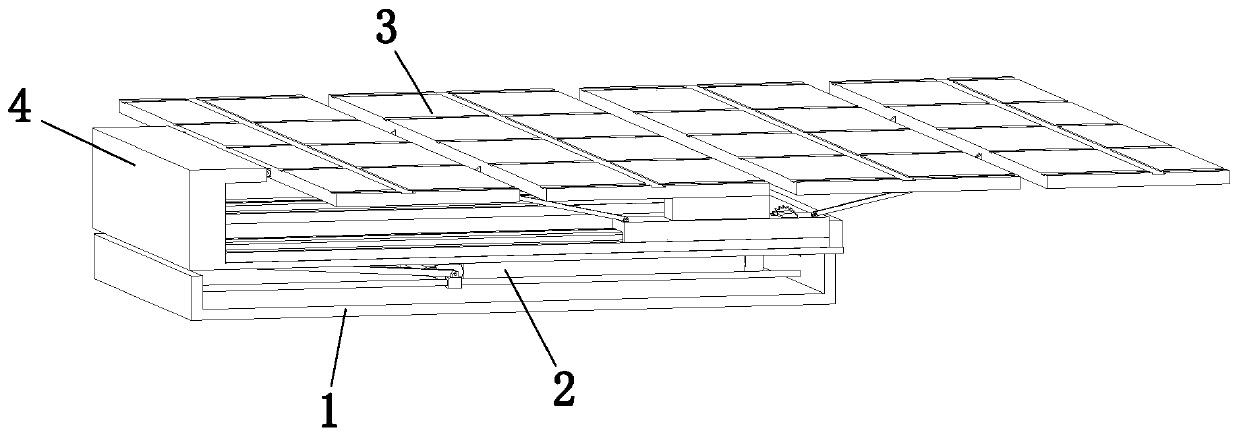
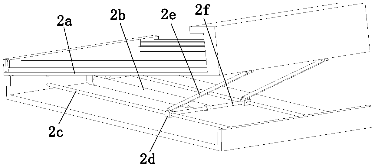
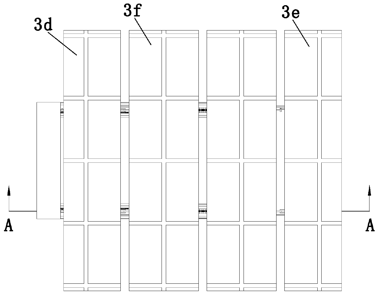
[0036] Combine below Figure 1 to Figure 7 As shown, the embodiment of the present invention provides a retractable solar panel with an angle adjustment function, including a base 1, an angle adjustment mechanism 2 and two folding mechanisms 3, the angle adjustment mechanism 2 is arranged on the upper end of the base 1, The two folding mechanisms 3 are symmetrically arranged on the upper end of the angle adjustment mechanism 2, the upper end of the angle adjustment mechanism 2 is provided with a support plate 4, and one end of the support plate 4 is fixedly connected with the two folding mechanisms 3, each The folding mechanism 3 includes a moving assembly 3a, a first folding assembly 3b, a second folding assembly 3c, a first solar panel 3d, a second solar panel 3e and two third solar panels 3f, and the moving assembly 3a is installed on The upper end of the angle adjustment mechanism 2, the first folding assembly 3b is installed on the top of the moving assembly 3a, the two t...

Embodiment 2

[0045] Refer to attached Figure 8 As shown, the moving assembly 3a includes a moving slide rail 3a6 and a moving slide block 3a7, the moving slide rail 3a6 is horizontally arranged on the upper end of the adjustment plate 2a, and the moving slide block 3a7 is installed on the moving slide rail 3a6 and moves Sliding fit between the slider 3a7 and the moving slide rail 3a6, a moving bar 3a8 for connecting the two moving sliders 3a7 in the two folding mechanisms 3 is provided, and the adjustment plate 2a is provided with a horizontally arranged The secondary electric push rod 3a9, the output end of the secondary electric push rod 3a9 is fixedly connected with the moving rod 3a8; the moving rod 3a8 is pushed to move through the work of the secondary electric push rod 3a9, and the moving rod 3a8 drives two moving sliders 3a7 Move along the length direction of the moving slide rail 3a6 to drive the moving assembly 3a, the first folding assembly 3b and the second folding assembly 3c...


PUM


Abstract

The invention discloses a telescopic solar panel with an angle adjusting function, and belongs to the technical field of solar panels. The telescopic solar panel comprises a base, an angle adjusting mechanism and two folding mechanisms. The upper end of the angle adjusting mechanism is provided with a support plate. Each folding mechanism comprises a moving assembly, a first folding assembly, a second folding assembly, a first solar panel, a second solar panel and two third solar panels. One side of the first solar panel is hinged with one end of the support plate, and the other end of the first solar panel is hinged with one side of one of the third solar panels. One side of the second solar panel is hinged with one side of the other third solar panel. The telescopic solar panel can automatically fold and unfold through working of the folding mechanisms so that the space occupation can be reduced, the wind receiving area and the dust falling area can be reduced, and thus the service life of the telescopic solar panel can be prolonged and the cleaning frequency can be reduced.

Description

technical field [0001] The invention relates to the technical field of solar panels, in particular to a retractable solar panel with an angle adjustment function. Background technique [0002] Solar energy is a kind of renewable energy. Solar energy is available everywhere, can be directly developed and utilized, is easy to collect, and does not need to be mined and transported. It is one of the cleanest energy sources and the total amount is the largest energy source that can be developed in the world today. With the development of science and technology, the methods and efficiency of people collecting and using solar energy are getting higher and higher. [0003] The Chinese patent number is CN106253810B, which discloses a movable telescopic device and a movable telescopic solar panel, which has: a translation part, including a fixed slide rail, two rollers respectively arranged at both ends of the slide rail, and a transmission belt sleeved on the two rollers , the slide...

Claims


Application Information

Patent Timeline
Patent Type & Authority Applications(China)
IPC IPC(8): H02S30/20H02S20/30F24S30/425F24S25/67
CPCF24S25/67F24S30/425H02S20/30H02S30/20Y02E10/47Y02E10/50
Inventor 姜寿保
Owner HANGZHOU YAOYAO PHOTOVOLTAIC TECH CO LTD
Learn More