
mobile lighting system

A technology of mobile lighting and telescopic poles, which is applied in the direction of instruments, supporting machines, mechanical equipment, etc., can solve the problems of high detection intensity, poor detection effect, single function, etc., and achieve the goal of reducing detection intensity, ensuring accuracy and improving detection efficiency Effect

Active Publication Date: 2022-07-26
深圳市海洋王铁路照明技术有限公司 +3
View PDF10 Cites 0 Cited by
  • Summary
  • Abstract
  • Description
  • Claims
  • Application Information

AI Technical Summary

Problems solved by technology

[0003] The purpose of the present invention is to provide a mobile lighting system, which aims to solve the technical problems of single function, high detection intensity and poor detection effect of the mobile lighting system in the prior art

Method used

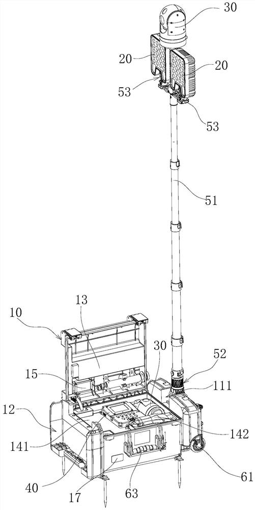
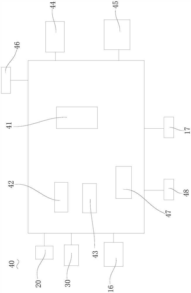
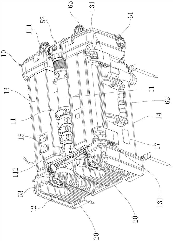

Image

  • mobile lighting system
  • mobile lighting system
  • mobile lighting system

Examples


Embodiment Construction

[0060] The following describes in detail the embodiments of the present invention, examples of which are illustrated in the accompanying drawings, wherein the same or similar reference numerals refer to the same or similar elements or elements having the same or similar functions throughout. Attached below by reference Figures 1 to 13 The described embodiments are exemplary and intended to explain the present invention and should not be construed to limit the present invention.

[0061] In the description of the present invention, it should be understood that the terms "length", "width", "upper", "lower", "front", "rear", "left", "right", "vertical", The orientations or positional relationships indicated by "horizontal", "top", "bottom", "inside", "outside", etc. are based on the orientations or positional relationships shown in the accompanying drawings, which are only for the convenience of describing the present invention and simplifying the description, rather than An in...


PUM


Abstract

The invention belongs to the technical field of lamps, and in particular relates to a mobile lighting system, comprising a base, a lamp head assembly, a camera assembly and a control device; the lamp head assembly is mounted on the base and used for emitting illumination light; the camera assembly is installed on the The base is used to collect image information; the control device is provided with an image recognition module for recognizing the image information, and the image recognition module is electrically connected to the camera assembly. The mobile lighting system uses the camera assembly and the image recognition module on the control device to realize the automatic identification and detection of the mobile lighting system. At the same time, the staff can only detect the detection parts or areas that do not meet the requirements according to the identification and detection results. The detection intensity of the staff can be reduced, the detection efficiency is improved, the missed detection is reduced, and the accuracy of the detection results can also be ensured, so that the mobile lighting system can realize rapid and intelligent maintenance.

Description

technical field [0001] The invention belongs to the technical field of lamps, and in particular relates to a mobile lighting system. Background technique [0002] Mobile lighting systems are used in railway inspections, public works inspections, train maintenance and other occasions that require emergency lighting. The existing mobile lighting system only has the function of lighting and does not have other functions, and the function is single; The work intensity of the staff is high, and the staff is prone to visual fatigue after working for a long time, resulting in the problems of poor detection effect and low accuracy. SUMMARY OF THE INVENTION [0003] The purpose of the present invention is to provide a mobile lighting system, which aims to solve the technical problems of single function, high detection intensity and poor detection effect of the mobile lighting system in the prior art. [0004] In order to achieve the above purpose, the technical scheme adopted in ...

Claims


Application Information

Patent Timeline
Patent Type & Authority Patents(China)
IPC IPC(8): G06V10/147G06V10/74G06V10/94G06V20/00G06K9/62G06K17/00G03B15/02F16M11/06
CPCG06K17/00G03B15/02F16M11/06G06V20/00G06V10/955G06V10/147G06F18/22
Inventor 周明杰周富友刘月舫
Owner 深圳市海洋王铁路照明技术有限公司
Learn More