
Welding robot vision assembly and measuring method thereof

A technology of welding robot and measurement method, which is applied in the direction of welding equipment, auxiliary welding equipment, welding/cutting auxiliary equipment, etc., can solve the problems of long teaching time, inability to weld accurately and reliably, and low degree of flexible welding, so as to achieve flexible The effect of increasing the height, realizing the flexibility and automation of welding operations, and solving the adaptability problem

Pending Publication Date: 2019-12-03
XIAN ZHONGKE PHOTOELECTRIC PRECISION ENG CO LTD
View PDF7 Cites 31 Cited by
  • Summary
  • Abstract
  • Description
  • Claims
  • Application Information

AI Technical Summary

Problems solved by technology

However, at present, welding robots generally need manual teaching, which seriously restricts the welding efficiency, which is even lower than that of manual welding. When the workpiece has blanking deviation, processing deviation, assembly deviation and clamping deviation, etc. Welding, making the welding robot unusable
In addition, the current welding robot mainly integrates mature laser seam sensors, but the premise of the work of the seam sensor is based on prior information (such as the shape of the seam, the approximate position of the starting point of the seam, etc.), the working process requires manual participation, and the seam sensor limited field of view
The above method makes the degree of flexible welding not high, and the welding path needs to be taught online manually during the welding process, and the teaching takes a long time, which cannot solve the problems of large workpiece blanking deviation, large alignment position deviation, and large clamping position deviation. flexible welding requirements

Method used


Image

  • Welding robot vision assembly and measuring method thereof
  • Welding robot vision assembly and measuring method thereof
  • Welding robot vision assembly and measuring method thereof

Examples


Embodiment Construction

[0071] The present invention will be described in detail below in conjunction with the accompanying drawings and specific embodiments, where the schematic embodiments and descriptions of the present invention are used to explain the present invention, but not to limit the present invention.

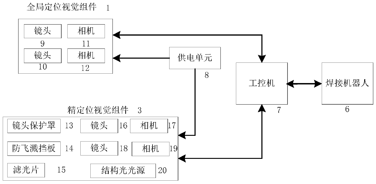
[0072] Such as figure 1 , figure 2 As shown, a welding robot vision component of the present invention includes a global positioning vision component 1, a global positioning vision component fixing bracket 2, a fine positioning vision component 3, a fine positioning vision component mounting bracket 4, a robot welding torch 5, a welding robot system 6, An industrial computer 7 and a power supply unit 8 .

[0073] The global positioning vision component 1 obtains the image information of the workpiece, sends the image information of the workpiece to the industrial computer, and then extracts the workpiece from the background of the welding workbench through the industrial computer, and r...


PUM


Abstract

The invention discloses a welding robot vision assembly and a measuring method thereof. The measuring method comprises the following steps: an industrial personal computer controls a global positioning vision assembly to collect workpiece image information and sends workpiece fine positioning measurement position information to a welding robot control system; the welding robot control system controls a welding gun of the welding robot to move a fine positioning visual assembly to a fine positioning measurement point; the industrial personal computer controls the fine positioning visual assembly to collect a workpiece weld joint image, calculates coordinates of a starting point and an ending point of a workpiece weld joint, and automatically generates a welding path of the workpiece weld joint; and the industrial personal computer guides the welding gun to move to a weld joint starting point for arc starting welding and to the ending point for arc extinguishing, and welding of the welding joint is completed. The welding robot vision assembly has the advantages of being free of teaching, high in welding efficiency, high in system tolerance and high in flexibility.

Description

technical field [0001] The invention belongs to the technical field of welding robots, and in particular relates to a welding robot vision component and a measuring method thereof. Background technique [0002] The welding robot system has been widely used in industrial sites. Compared with manual welding, it has the advantages of stable and reliable welding quality, good consistency, continuous work, and labor saving. However, at present, welding robots generally need manual teaching, which seriously restricts the welding efficiency, which is even lower than that of manual welding. When the workpiece has blanking deviation, processing deviation, assembly deviation and clamping deviation, etc. Welding, making the welding robot unusable. In addition, the current welding robot mainly integrates mature laser seam sensors, but the premise of the work of the seam sensor is based on prior information (such as the shape of the seam, the approximate position of the starting point o...

Claims


Application Information

Patent Timeline
IPC IPC(8): B25J19/04B25J9/16B25J11/00B23K37/00
CPCB25J19/04B25J9/16B25J11/00B23K37/00Y02P90/02
Inventor 赵晓进陈武强吴易明王永旺黄荣董林佳靳亚丽摆冬冬
Owner XIAN ZHONGKE PHOTOELECTRIC PRECISION ENG CO LTD
Learn More