
Indexable blade grinding positioning error compensation method

A technology of positioning error and indexing blades, which is applied to the parts of grinding machine tools, grinding/polishing equipment, complex mathematical operations, etc., can solve the problems that non-standard blades cannot be ground normally, so as to save man-hours and reduce work intensity , the effect of improving efficiency

Inactive Publication Date: 2019-12-03
陕西汉江机床有限公司 +1
View PDF0 Cites 4 Cited by
  • Summary
  • Abstract
  • Description
  • Claims
  • Application Information

AI Technical Summary

Problems solved by technology

[0003] The purpose of the present invention is to solve the above-mentioned problems in the prior art, to provide a compensation method for indexable insert grinding positioning errors, which does not require a lot of man-hours to adjust the length of the tip, saves time, improves the versatility of the tip at the same time, reduces costs, and especially solves the problem of The problem that non-standard inserts with multiple relief angles cannot be ground normally

Method used


Image

  • Indexable blade grinding positioning error compensation method
  • Indexable blade grinding positioning error compensation method
  • Indexable blade grinding positioning error compensation method

Examples


Embodiment Construction

[0019] In order to make the technical problems, technical solutions and beneficial effects to be solved by the present invention clearer and clearer, the present invention will be further described in detail below in conjunction with the accompanying drawings and embodiments.

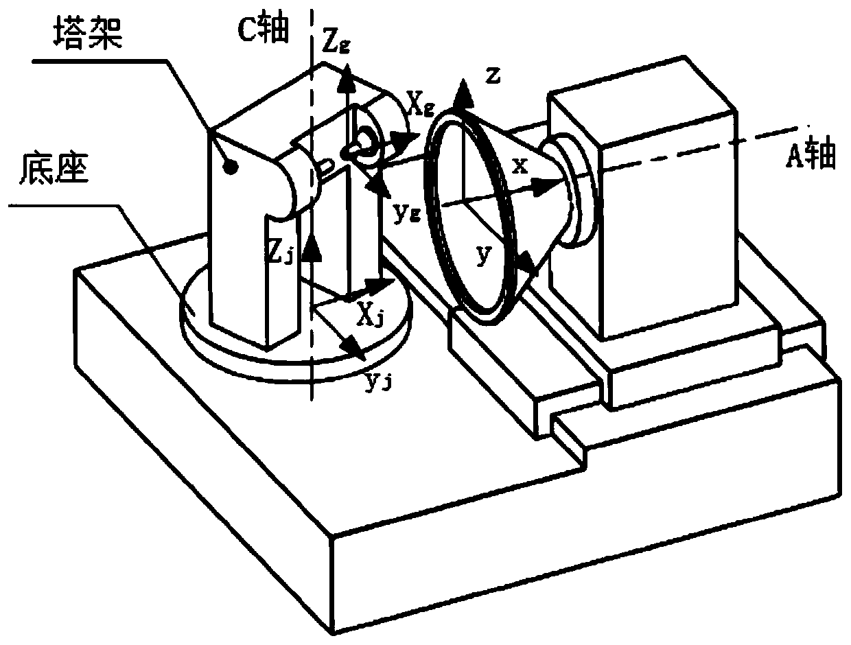
[0020] Such as Figure 1-7 As shown, the indexable insert grinding positioning error compensation method includes the following steps:

[0021] 1) Establish the workpiece coordinate system {x g ,y g ,z g}, the tower coordinate system {x j ,y j ,z j}, the machine tool coordinate system {x, y, z} whose origin is the intersection point of the grinding wheel rotation axis A-axis and the plane where the grinding wheel end face is located, and make the workpiece coordinate system, tower coordinate system and machine tool coordinate system X-axis, Y-axis, The direction of the Z axis is the same;

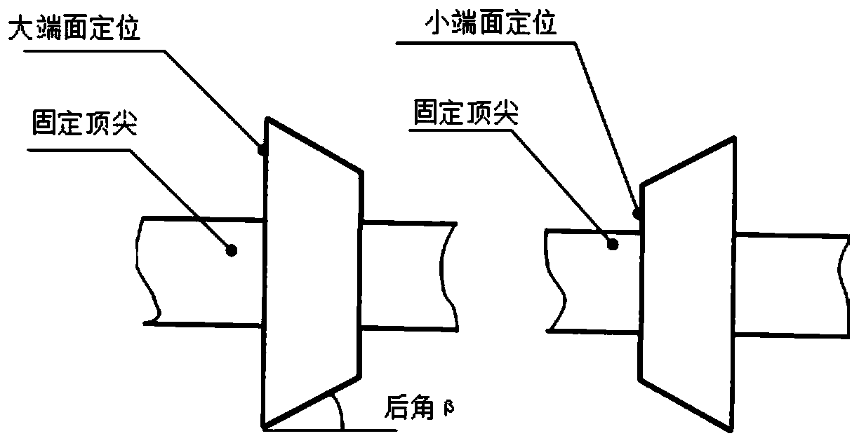
[0022] 2) Position the standard square insert with a relief angle of β on the large end face and the small ...


PUM


Abstract

The invention discloses an indexable blade grinding positioning error compensation method and belongs to the field of cutter grinding. The method comprises steps of firstly, establishing a workpiece coordinate system, a tower coordinate system and a machine tool coordinate system; clamping a standard square blade with a relief angle beta between the two tips, acquiring coordinate values of a linear edge of the square blade in a machine tool coordinate system in the X direction when a C axis turns to -beta and beta respectively by adopting contact measurement, and calculating deviation values of a rotation center of the end surface of the fixed tip and a rotation center of the tower in the X and Y directions according to the measured values; calculating a conversion relation from the workpiece coordinate system to a tower coordinate system and a machine tool coordinate system according to the deviation value; and finally, calculating a positioning error compensation formula of the relief angle blade and the chamfering blade and compensating the error into a blade grinding theoretical calculation formula. Error automatic compensation is adopted, the requirement for machine tool assembling precision is greatly lowered, on the premise that the blade machining precision is guaranteed, the blade replacing efficiency is improved, working hours are greatly saved, cost is reduced, and meanwhile the working intensity of workers is lowered.

Description

technical field [0001] The invention relates to the field of tool grinding, in particular to a method for compensating positioning errors in grinding of indexable inserts. Background technique [0002] There are many types of indexable blades, and the use of peripheral edge grinders should facilitate the replacement of various blades. In the peripheral grinding machine, the tower for clamping the blade is composed of two parts: 1. The fixed top part and the floating top part are used to clamp the blade. The center of rotation of the fixed top end face is the center of the blade positioning end face and the center of the workpiece coordinate system calculated by theoretical coordinates; 2. The part of the tower that rotates around the base is used for grinding blades with rear angles. The axis of rotation around is called the C-axis, and the intersection of the C-axis and the base is the center of rotation of the tower. The center of the fixed top end surface should coincid...

Claims


Application Information

Patent Timeline
IPC IPC(8): B24B3/36B24B49/04G06F17/16
CPCB24B3/36B24B49/04G06F17/16
Inventor 李军姚斌贺文辉郑清陈彬强
Owner 陕西汉江机床有限公司
Learn More