A movable plug pressing die

A press-forming and movable technology, applied in the field of press-forming molds, can solve problems such as difficulty in guaranteeing normal production of enterprises, high production costs and manufacturing costs, and the need to redo the entire set of molds, etc., to overcome manufacturing difficulties, short manufacturing cycle, Solve the effect of difficult processing

Active Publication Date: 2020-08-25
湖南华冉科技有限公司
View PDF5 Cites 0 Cited by
  • Summary
  • Abstract
  • Description
  • Claims
  • Application Information

AI Technical Summary

Problems solved by technology

[0003] In the process of processing a plug product produced by our company, the following technical problems were found: 1. The ordinary plug forming mold has an integrated design during processing, which is difficult to operate and has poor stability during product processing. The processing efficiency is low, and the punch and thimble mold need to be replaced frequently. Once damaged or worn, the whole mold can only be redone. The maintenance cost is high and the manufacturing cycle is long, which brings a large production cost and manufacturing cost to the company; 2. The processing is small For the plug parts of different sizes, it is necessary to use high-precision wire cutting to cut and shape the forming lower mold and to use high-precision electric sparks for drilling. The processing is difficult and the processing cost is high. Therefore, in the case of wear and loss of the mold, it cannot be replenished and replaced in time, and it is difficult to guarantee the normal production of the enterprise. Therefore, our company independently developed a set of special molds for plug pressing and forming.

Method used


Image

  • A movable plug pressing die
  • A movable plug pressing die
  • A movable plug pressing die

Examples


Embodiment Construction

[0029] In order to enable those skilled in the art to better understand the technical solution of the present invention, the present invention will be described in detail below in conjunction with the accompanying drawings. The description in this part is only exemplary and explanatory, and should not have any limiting effect on the protection scope of the present invention. .

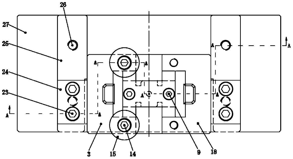
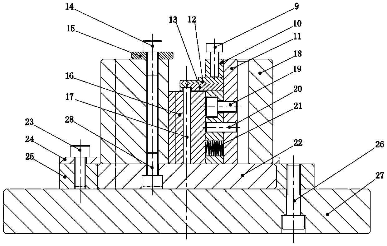
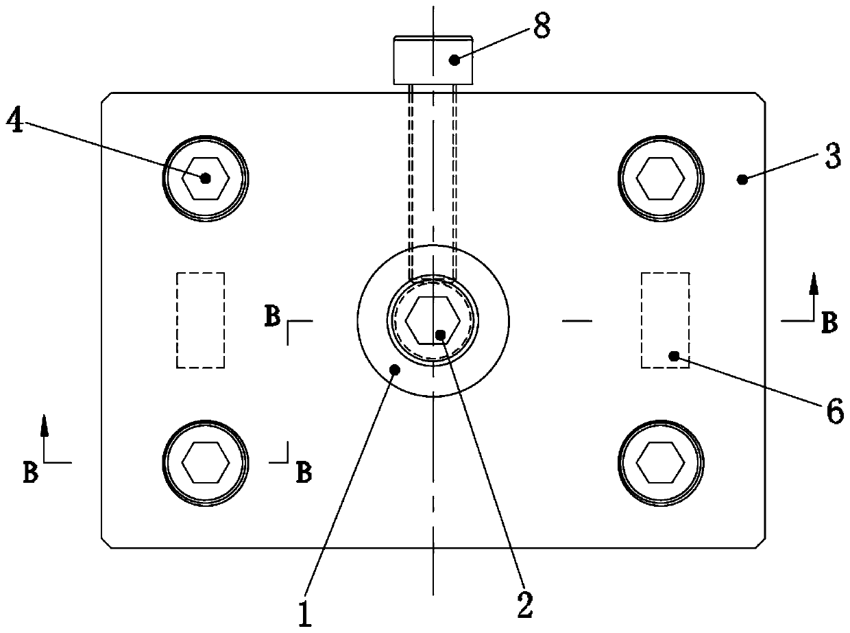
[0030] like Figure 1-Figure 10 As shown, the specific structure of the present invention is: a movable plug press molding die, which includes an upper die assembly and a lower die assembly, the upper die assembly includes a die handle 1, and a countersunk threaded hole is set in the middle of the die handle 1 And the upper mold body 3 is fixedly connected by the first bolt 2, and the upper mold body 3 is fixedly connected with the upper splint 5 by four second bolts 4. The upper splint 5 is symmetrically provided with guide posts 6 inside, and the middle part of the upper splint 5 is vertically penetr...


PUM


Abstract

The invention discloses a movable plug compression molding die. The die comprises an upper die assembly and a lower die assembly, the upper die assembly comprises a die handle, the die handle is fixedly connected with an upper die body through a first bolt, the upper die body fixes an upper clamping plate through a second bolt, a guide column is arranged in the upper clamping plate, a forming upper male die is arranged in the middle of the upper clamping plate, and a first puller bolt is longitudinally arranged at the side end of the upper die body and abuts against the forming upper male die;the lower die assembly comprises a lower die base, guide blocks are symmetrically and fixedly arranged at the top of the lower die base through sixth bolts, the guide blocks fix a baffle through fifth bolts, a sliding plate is fixedly connected with the lower die above through four seventh bolts, a guide column groove and a side plate mounting groove are formed in the lower die, an inlaying groove is formed in the middle of the lower die, and an insert is arranged in the inlaying groove. According to the invention, a split type design is adopted, a conventional integrated design is replaced by an insert combination form, the manufacturing period is short, the production efficiency is high, the operation is easy, the use is simple, the reliability is high, the service life period of the mold is long, and the adaptability is strong.

Description

technical field [0001] The invention relates to the technical field of compression molding dies, in particular to a movable plug compression molding die. Background technique [0002] The plug is used to block the opening that does not need to be used, and it has the same function as the blind plate, the head and the pipe cap. [0003] In the process of processing a plug product produced by our company, the following technical problems were found: 1. The ordinary plug forming mold has an integrated design during processing, which is difficult to operate and has poor stability during product processing. The processing efficiency is low, and the punch and thimble mold need to be replaced frequently. Once damaged or worn, the whole mold can only be redone. The maintenance cost is high and the manufacturing cycle is long, which brings a large production cost and manufacturing cost to the company; 2. The processing is small For the plug parts of different sizes, it is necessary ...

Claims


Application Information

Patent Timeline
Patent Type & Authority Patents(China)
IPC IPC(8): B21D37/10B21D37/12
CPCB21D37/10B21D37/12
Inventor 但红梅唐江军敖洪王洪胜刘西聂理
Owner 湖南华冉科技有限公司
Why Eureka
Try Eureka